Figure 2-4, Component locations – ADLINK ReadyBoard 910 User Manual
Page 17
Chapter 2
Product Overview
ReadyBoard 910
Reference Manual
11
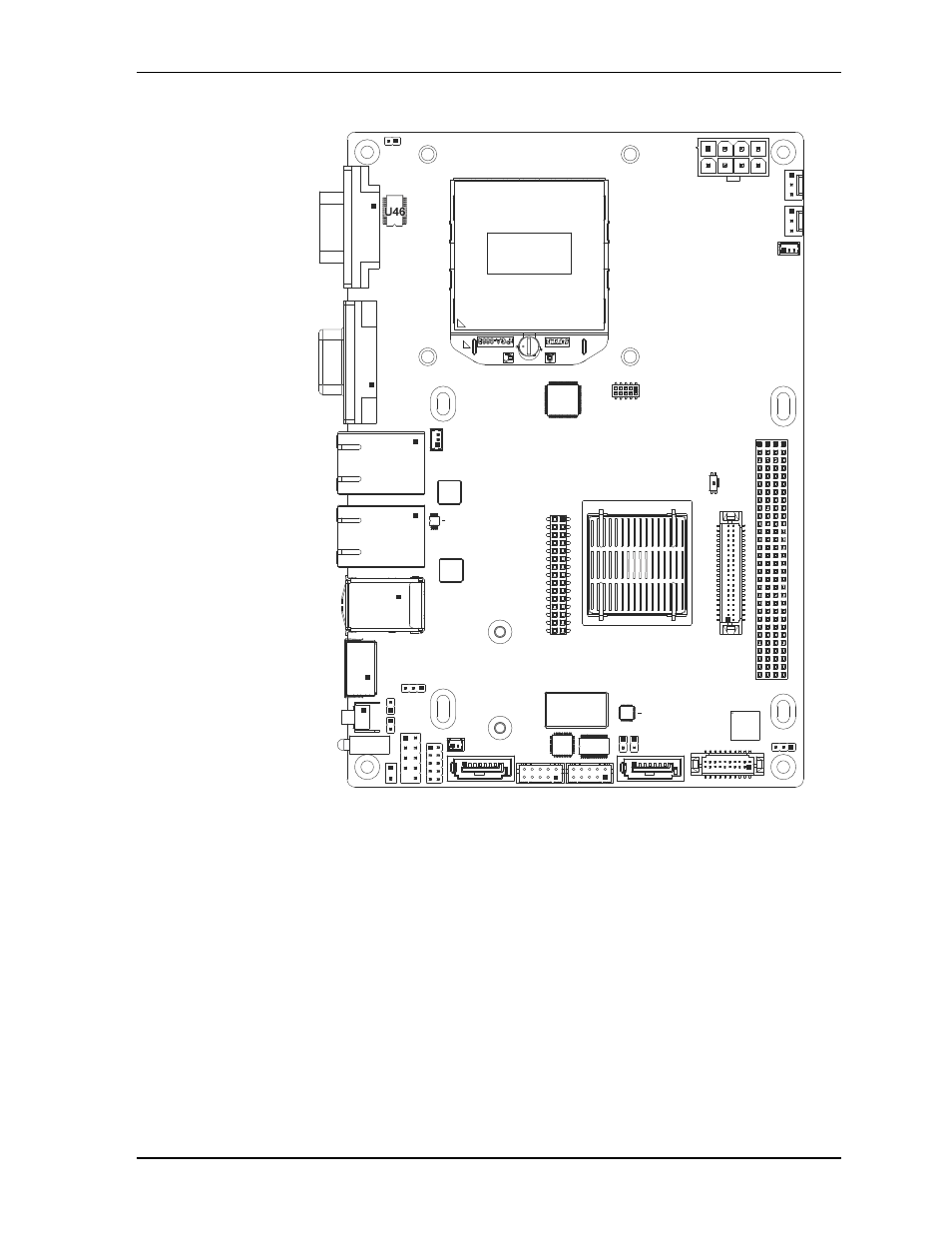
Figure 2-4. Component Locations
U38
U22
U25
U26
U15
U33
U30
U34
U46
U18
RB910_T
op_Comp_b
Key:
U5 - PCIe-to-PCI Bridge
U15 - PCH
U18 - TMDS Level Shifter
U22 - RS-485/422
Transceiver - COM0-1
U24 - Super I/O
U25 - SSD
U26 - Audio Codec
U30 - CPU
U33 - Gb Ethernet Controller - GLAN1
U34 - Gb Ethernet Controller - GLAN2
U38 - Ethernet EEPROM - GLAN1
U46 - RS-232 Transceiver - COM0-1
U24
U5
See also other documents in the category ADLINK Hardware:
- USB-1901 (84 pages)
- USB-1210 (54 pages)
- USB-2401 (60 pages)
- USB-7230 (50 pages)
- USB-2405 (56 pages)
- DAQe-2010 (92 pages)
- DAQe-2204 (100 pages)
- DAQe-2213 (94 pages)
- DAQe-2501 (74 pages)
- PXI-2010 (84 pages)
- PXI-2020 (60 pages)
- PXI-2501 (62 pages)
- cPCI-9116 (98 pages)
- ACL-8112 Series (93 pages)
- ACL-8112 Series (94 pages)
- ACL-8112 Series (92 pages)
- ACL-8216 (75 pages)
- ACL-8111 (61 pages)
- PCM-9112+ (10 pages)
- PCM-9112+ (94 pages)
- cPCI-6216V (47 pages)
- ACL-6126 (28 pages)
- ACL-6128A (40 pages)
- PCM-6308V+ (52 pages)
- PCM-6308V+ (4 pages)
- PCI-7444 (82 pages)
- PCI-7434 (48 pages)
- PCI-7234 (56 pages)
- PCI-7260 (66 pages)
- PCI-7258 (38 pages)
- PCI-7256 (48 pages)
- PCI-7250 (48 pages)
- LPCI-7250 (48 pages)
- PCI-7396 (65 pages)
- PCI-7296 (59 pages)
- PCI-8554 (67 pages)
- PCIe-7360 (94 pages)
- PCIe-7350 (86 pages)
- PCIe-7300A (114 pages)
- PCIe-7200 (51 pages)
- PCI-7300A (112 pages)
- PCI-7300A (83 pages)
- PCI-7200 (96 pages)
- cPCI-7300 (82 pages)
- cPCI-7300 (83 pages)