Ext interface, Table 3-10, Ext interface pin signal descriptions (cn9) – ADLINK ReadyBoard 910 User Manual
Page 37
Chapter 3
Hardware
ReadyBoard 910
Reference Manual
31
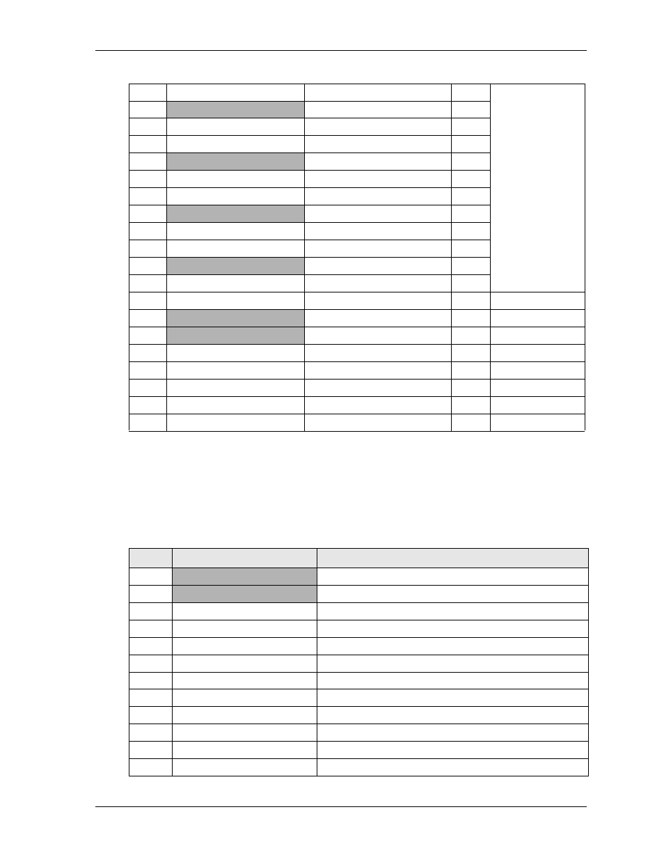
Note: The shaded table cells denote power or ground.
EXT Interface
The EXT header provides signals for optional CAN and Serial Telecom modules.
signals for the EXT interface female header, which provides 30 pins in two rows with odd/even (1,2)
sequence and 0.079" (2mm) pitch.
23
LB_DATA0_P
Data Positive Output
0
Channel 2
24
GND
Ground
25
LB_DATA0_N
Data Negative Output
0
26
LB_DATA1_P
Data Positive Output
1
27
GND
Ground
28
LB_DATA1_N
Data Negative Output
1
29
LB_DATA2_P
Data Positive Output
2
30
GND
Ground
31
LB_DATA2_N
Data Negative Output
2
32
LB_DATA3_P
Data Positive Output
3
33
GND
Ground
34
LB_DATA3_N
Data Negative Output
3
35
LCD_BLON
Backlight Enable
NA
36
GND
Ground
37
GND
Ground
38
LDDC_DATA
Display Data Channel Data
NA
NA
39
LCD_BLCTL
Control Panel Backlight
NA
NA
40
LDDC_CLOCK
Display Data Channel Clock
NA
NA
41
NC
Not Connected
NA
NA
42
NC
Not Connected
NA
NA
Table 3-10. EXT Interface Pin Signal Descriptions (CN9)
Pin #
Signal
Description
1
GND
2
P3V3_S
+3.3 Volts Power Standby
3
LPC_AD3
Multiplexed Command, Address, and Data
4
LPC_FRAME
Indicates start of a new cycle or termination of broken cycle
5
LPC_AD2
Multiplexed Command, Address, and Data
6
CLK33_CANBUS
CAN Bus Clock Signal
7
LPC_AD1
Multiplexed Command, Address, and Data
8
CANBUS_RST-L
CAN Bus Reset Low
9
LPC_AD0
Multiplexed Command, Address, and Data
10
CANBUS_DISABLE-L
CAN Bus Disable Low
11
S2_RXD
Serial Receive Data
12
WL_ON_OFF
Power Good
Table 3-9. LVDS Interface Pin Signals (CN5)
(Continued)