Power interfaces, Power in power on, Table 3-17 – ADLINK ReadyBoard 910 User Manual
Page 42: Power in pin signal descriptions (cn3), Table 3-18, Power on header pin signal descriptions (cn1)
Chapter 3
Hardware
36
Reference Manual
ReadyBoard 910
Power Interfaces
The ReadyBoard 910 uses various voltages onboard and externally receives +12 volts through the external
Power In (CN3) interface, which uses an 8-pin header with 0.165" (4.2 mm) pitch. The +12V is provided for
the CPU Fan, System Fan, LVDS power, PCI-104 bus, and PCIe Mini Card power. All other onboard
voltage requirements, including the CPU core voltages are met with +5 volts DC +/- 5%, derived from the
externally supplied +12 volts.
Power In
lists the pin signals for Power In header (CN3), which provides 8 pins in two rows with
consecutive (1,6) pin sequence and 0.165" (4.2mm) pitch.
Note: The shaded table cells denote power or ground.
Power On
The signals on this header allow the ATX power supply to be turned off (soft off) from the ReadyBoard 910
by operating system (OS) control. However, if you use a non-ATX power supply, then you will not have the
soft off feature for sleep states normally provided by ATX power supplies. Use the JP4 jumper to select
Power On options (S3/S5).
provides the pin signal names and descriptions of the Power On
interface, which provides a 3-pin shrouded header with 0.049" (1.25mm) pitch
Note: The shaded table cells denote power or ground. The signals marked with * indicate the signal is
Active Low.
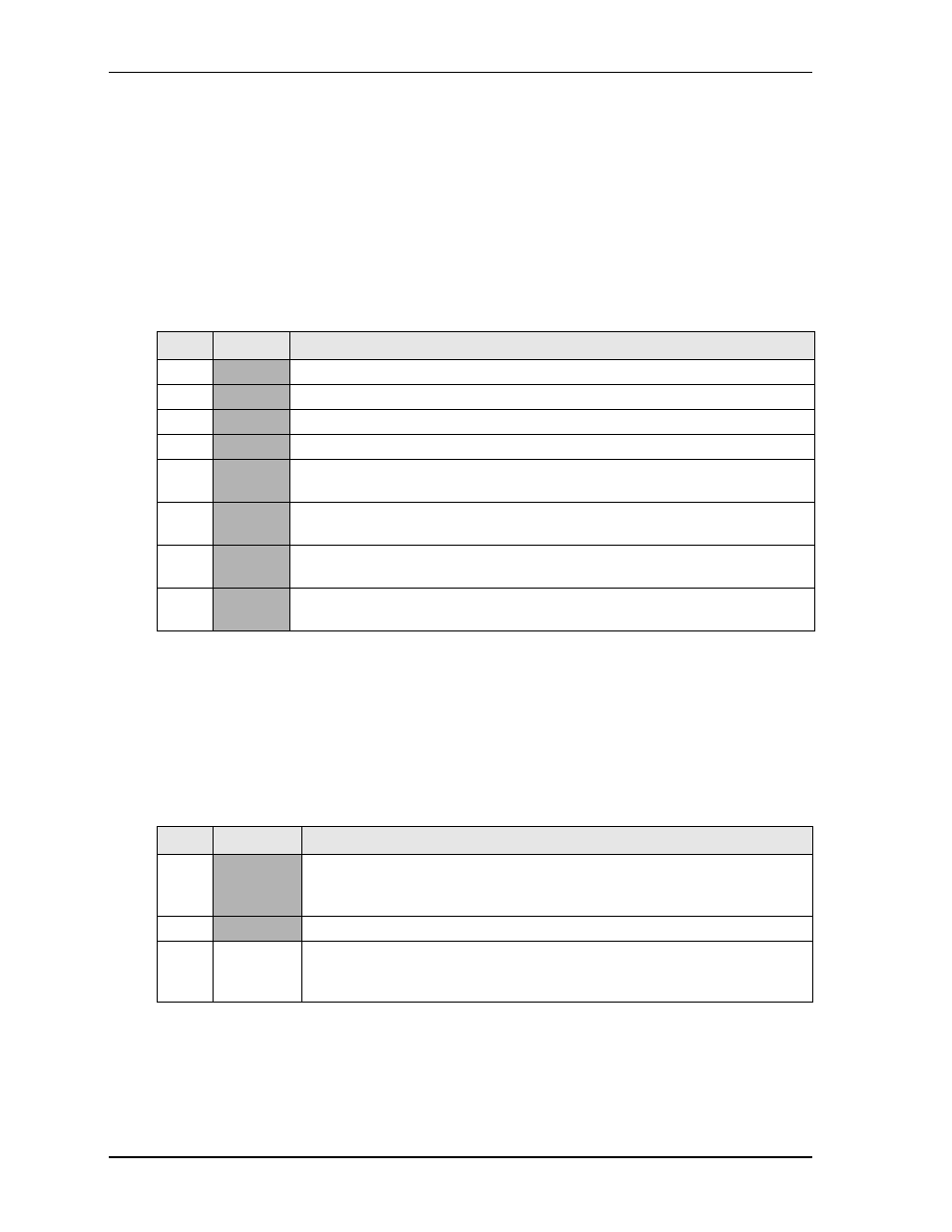
Table 3-17. Power In Pin Signal Descriptions (CN3)
Pin #
Signal
Description
1
GND
Ground
2
GND
Ground
3
GND
Ground
4
GND
Ground
5
+12V
This +12 voltage is primarily for the PCI-104 bus, PCIe Mini Card, CPU fan,
System fan, and LVDS power (may also be backlight power).
6
+12V
This +12 voltage is primarily for the PCI-104 bus, PCIe Mini Card, CPU fan,
System fan, and LVDS power (may also be backlight power).
7
+12V
This +12 voltage is primarily for the PCI-104 bus, PCIe Mini Card, CPU fan,
System fan, and LVDS power (may also be backlight power).
8
+12V
This +12 voltage is primarily for the PCI-104 bus, PCIe Mini Card, CPU fan,
System fan, and LVDS power (may also be backlight power).
Table 3-18. Power On Header Pin Signal Descriptions (CN1)
Pin #
Signal
Description
1
VCC5
+5V Voltage – This voltage (refer to ATX Specification 2.2 or later for
minimum requirement) is supplied from the ATX power supply and is required
for normal operation and sleep states.
2
GND
Ground
3
PS_ON*
Power Supply On – This signal is sent to the ATX power supply from the
ReadyBoard 910 to turn on the ATX power supply. This signal can also be used
to turn off the ATX power supply or go into a suspended or standby state.