Table 3-11, Miscellaneous – ADLINK ReadyBoard 910 User Manual
Page 38
Chapter 3
Hardware
32
Reference Manual
ReadyBoard 910
Miscellaneous
SSD (Solid State Drive)
The ReadyBoard 910 provides a 4GB SSD, which is soldered directly onto the board. For more information
refer to the SSD data sheet:
http://www.greenliant.com/products/?inode=47717
.
Real Time Clock (RTC)
The ReadyBoard 910 contains a Real Time Clock (RTC). The CMOS RAM is backed up with a Lithium
Battery. If the battery is not present, a battery-free boot option in the BIOS completes the boot process and
resets the clock to the default date and time.
External Battery
An external battery input connection is provided through the battery connector (CN12) for an external
battery. The external battery is used to power the Real Time Clock. ADLINK provides a small 3.0 volt
battery, adhered to the board and connected to the external battery header.
Note: The shaded table cells denote power or ground. The RTC has an expected current draw of 6
A at
room temperature. The battery is used only when power is not applied to the board.
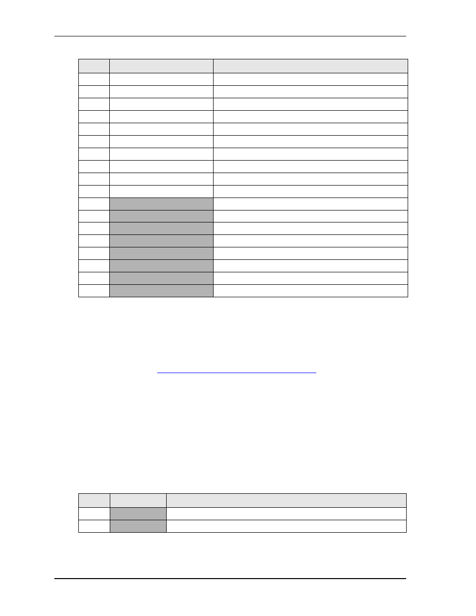
13
S2_TXD
Serial Transmit Data
14
WL_RST-L
Power Reset Low
15
S2_RTS-L
Serial Request To Send Low
16
PCH_GPIO36
GPIO 3.3V Standby
17
S3_RXD
Serial Receive Data
18
PCH_GPIO37
GPIO 3.3V Standby
19
S3_TXD
Serial Transmit Data
20
PCH_GPIO38
GPIO 3.3V Standby
21
SIO_SERIRQ
Super IO Serial IRQ for Interrupt Support
22
PCH_GPIO39
GPIO 3.3V Standby
23
GND
Ground
24
GND
Ground
25
GND
Ground
26
GND
Ground
27
P5V_S
+5 Volts Power Standby
28
P5V_S
+5 Volts Power Standby
29
P5V_S
+5 Volts Power Standby
30
P5V_S
+5 Volts Power Standby
Note: The shaded table cells denote power or ground.
Table 3-11. External Battery Interface Pin Signal Descriptions (CN12)
Pin #
Signal
Description
1
PVBAT
+3.0 Volts Power
2
GND
Ground
Table 3-10. EXT Interface Pin Signal Descriptions (CN9) (Continued)
Pin #
Signal
Description