Serial interfaces – ADLINK ReadyBoard 910 User Manual
Page 31
Chapter 3
Hardware
ReadyBoard 910
Reference Manual
25
Serial Interfaces
The Super I/O (SCH3114I-NU) chip provides the circuitry for the two serial ports. The Super I/O chip
provides serial port 1 through a standard DB9 connector (CN17) and serial port 2 through a 10-pin header
(CN8). The two serial ports support the following features:
•
Four individual 16550-compatible UARTs
•
Programmable word length, stop bits and parity
•
16-bit programmable baud rate generator
•
Interrupt generator
•
Loop-back mode
•
Four individual 16-bit FIFOs
•
Serial Interface
Serial Port 1 (COM0) supports RS-232/RS-485/RS-422 and full modem support
Serial Port 2 (COM1) supports RS-232/RS-485/RS-422 and full modem support
To implement the two-wire RS-485 mode on serial ports 1 or 2, you must tie the equivalent pins together for
the selected port.
For example, on Serial Port 2, tie pin 3 to 5 and pin 4 to 6 on the Serial 2 (COM1) interface header as shown
. As an alternate, tie pin 2 to 3 and pin 7 to 8 on the DB9 connector for serial port 1 (COM0) as
shown in
. Refer to
for the specific pin signals of serial port 2. The corresponding pins
on the DB9 serial 1 connector are also available in
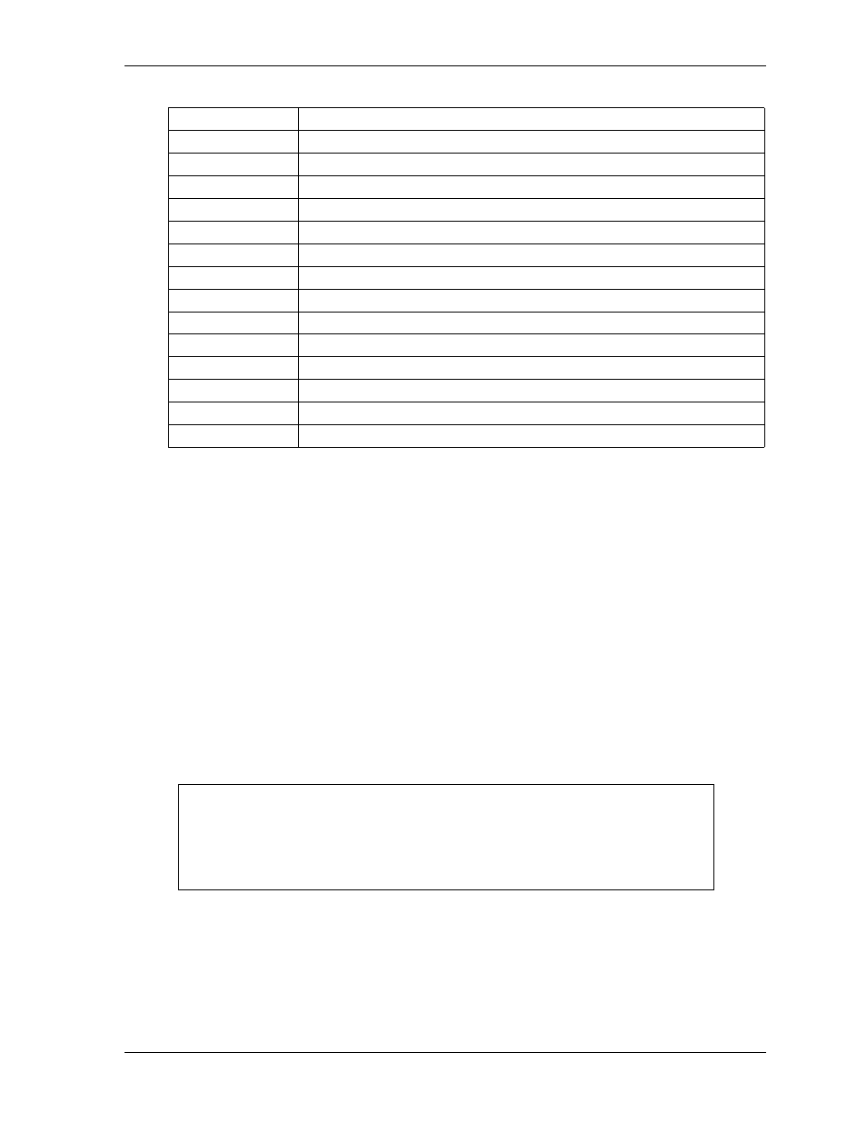
0090-0091
System reserved
0092
Fast A20 gate and CPU reset
0093-009F
System reserved
00A0-00A1
Slave Interrupt Controller
00A2-00BF
System reserved
00C0-00DF
Slave DMA Controller #2
00E0-00EF
System reserved
00F0-00FF
Math Coprocessor
01F0-01F7
SATA Controller
02F8-02FF
Serial Port 2 (COM2)
03B0-03BB
Video (monochrome)
03C0-03DF
Video (VGA)
03F8-03FF
Serial Port 1 (COM1)
04D0-04D1
Edge/Level Trigger PIC
0CF9
Reset Control Register
NOTE
The RS-232/RS-485/RS-422 modes are selected in BIOS Setup under the
Advanced/Super I/O Configuration menu However, the RS-232 mode is the
default (Standard) for any serial port.
RS-485 mode termination is selected with jumper header JP2 (COM0), and JP3
(COM1), when the RS-485 mode is selected in BIOS Setup.
Table 3-3. I/O Address Map (Continued)