Dvi interface, Table 3-8, Dvi pin signal descriptions (cn4) – ADLINK ReadyBoard 910 User Manual
Page 35
Chapter 3
Hardware
ReadyBoard 910
Reference Manual
29
•
Provide plug and play capabilities (EDID and DDC2B)
LVDS Flat Panel features:
•
Support an integrated dual channel LFP Transmitter interface
•
Support LVDS LCD panel resolutions up to 1920x1080 at 60Hz
•
Support for a maximum pixel format of 18 bpp with SSC supported frequency range from 25 MHz to
112 MHz (single channel/dual channel)
•
Support for 1 or 2 channel LVDS output
•
Support the LVDS port independently or simultaneously with the Analog Display (CRT) port
•
Support Spread Spectrum Clocking; center and down spread support utilizing an external SSC clock
•
Support panel up-scaling (to fit a smaller source image onto a specific native panel size) as well as
panning and centering CRT interface
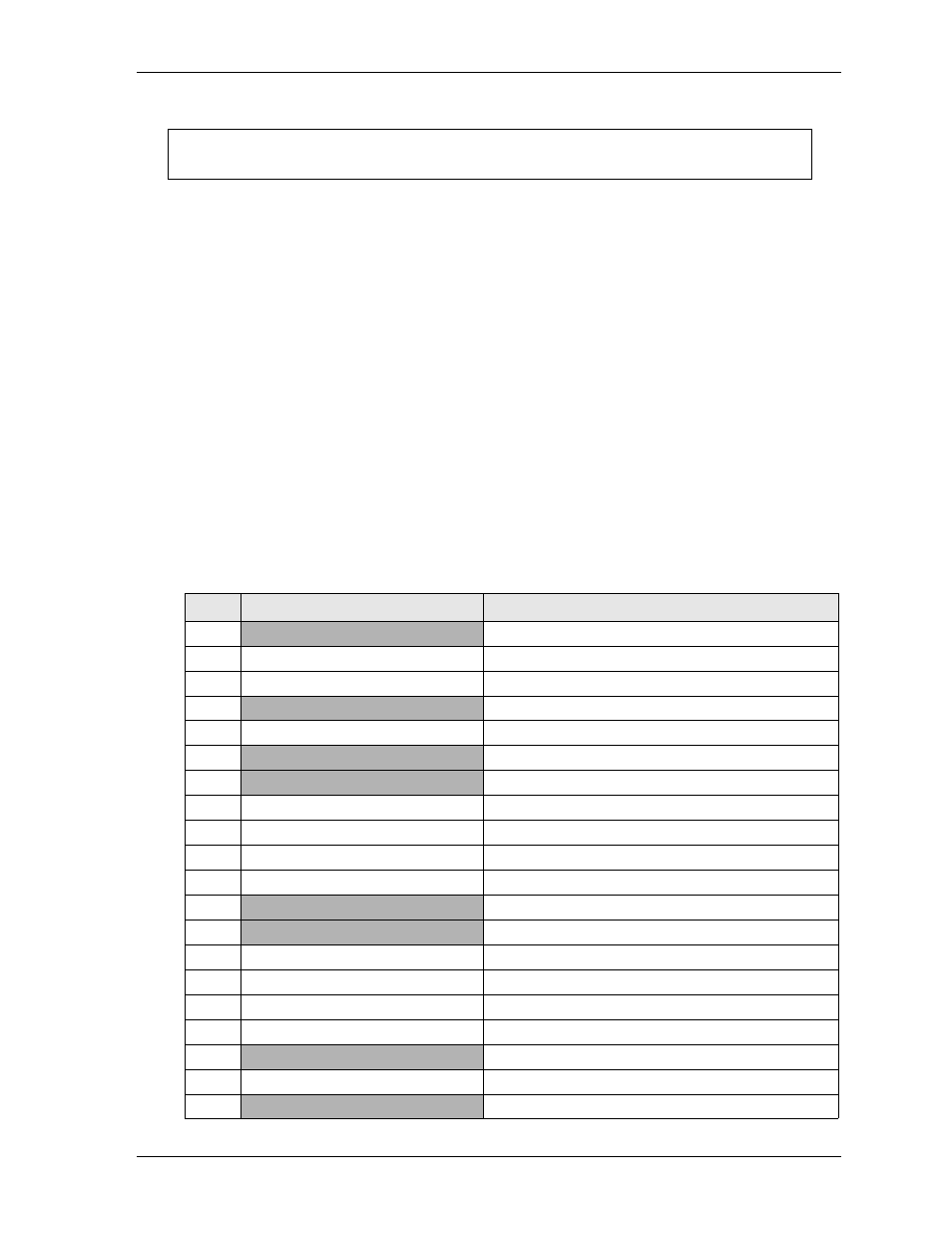
DVI Interface
This header provides the capacity to bring out the TMDS signals to a DVI (Digital Visual Interface)
connector.
lists the pin signals for the DVI header, which provides 22 pins, two rows, odd/even pin
sequence with 0.049" (1.25mm) pitch.
NOTE
The ReadyBoard 910 DVI support is only for DVI-D signals. The cable kit for this
product only provides a DVI-I cable, but the cable is compatible with DVI-D signals.
Table 3-8. DVI Pin Signal Descriptions (CN4)
Pin #
Signal
Description
1
GND
Digital Ground
2
NC
Not Connected
3
TMDSDVI_DATA0_N
TMDS Data 0 Negative
4
VDD_+5V
+5 Volts Power
5
TMDSDVI_DATA0_P
TMDS Data 0 Positive
6
GND
Digital Ground
7
GND
Digital Ground
8
TMDSDVI_DATA1_P
TMDS Data 1 Positive
9
TMDSDVI_DATA2_P
TMDS Data 2 Positive
10
TMDSDVI_DATA1_N
TMDS Data 1 Negative
11
TMDSDVI_DAT2_N
TMDS Data 2 Negative
12
GND
Digital Ground
13
GND
Digital Ground
14
TMDSDVI_CLOCK_P
TMDS Clock Positive
15
DVI_SCL_CN
Serial Clock - DDC (I2C)
16
TMDSDVI_CLOCK_N
TMDS Clock Negative
17
DVI_SDA_CN
Serial Data - DDC (I2C)
18
GND
Digital Ground
19
DVI_HPD_CN
Hot Plug Detect - DDC (I2C)
20
GND
Digital Ground