Video interfaces, Table 3-6, Audio pin signal descriptions (cn10) – ADLINK ReadyBoard 910 User Manual
Page 34: Table 3-7, S/pdif digital audio pin signals (cnx1)
Chapter 3
Hardware
28
Reference Manual
ReadyBoard 910
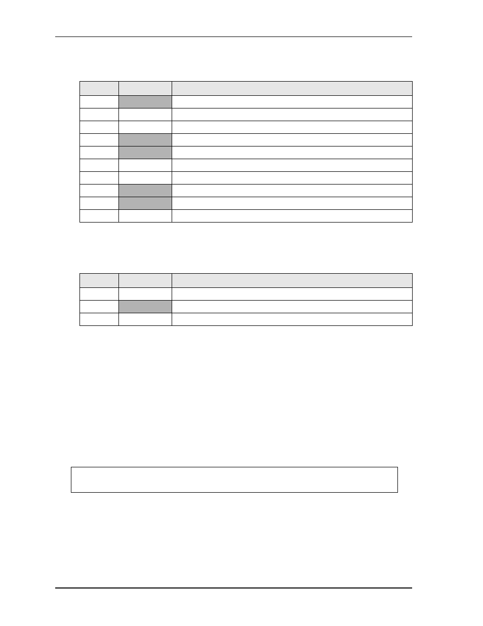
lists the pin signals for the Digital Audio header, which provides 10 pins, two rows, odd/even pin
sequence with 0.079" (2mm) pitch.
Note: The shaded table cells denote ground.
lists the pin signals for the S/PDIF Digital Audio header, which provides 3 pins, single row with
0.049" (1.25mm) pitch.
Note: The shaded table cell denotes ground.
Video Interfaces
The PCH, BD82HM65 provides the video interfaces for traditional CRT monitors, DVI high-resolution
displays, and LVDS flat panel displays. The Video Interface features are listed below.
VGA features:
•
Provides a standard DB15 connector interface, which delivers RGB, HSYNC, VSYNC, and DDC
signals
•
Support for an integrated 340.4-MHz, 24-bit RAMDAC to drive a progressive scan analog monitor and
outputs to three, 8-bit DACs that provide the R, G, and B signals to the monitor
•
Support for resolutions up to 2048x1536 with 32-bit color at 75Hz refresh
DVI features:
•
Support DVI resolutions up to 1920x1200 at 60Hz refresh
•
Provide Hot Plug detect for guaranteed “input LOW” when not connected
•
Support lossless (digital) transmission of video signals
•
Support display hardware independence
Table 3-6. Audio Pin Signal Descriptions (CN10)
Pin #
Signal
Description
1
GND_AUD
Ground
2
LINEOUT-L
Line Out signal left channel
3
LINEOUT-R
Line Out signal right channel
4
GND_AUD
Ground
5
GND_AUD
Ground
6
LINEIN-L
Line In signal left channel
7
LINEIN-R
Line In signal right channel
8
GND_AUD
Ground
9
GND_AUD
Ground
10
MIC
Stereo microphone In
Table 3-7. S/PDIF Digital Audio Pin Signals (CNX1)
Pin #
Signal
Description
1
SPDIF_OUT
Digital Audio Out
2
GND
Ground
3
SPDIF_IN
Digital Audio In
NOTE
The VGA connector is standard, and this manual does not provide signal descriptions for
standard interfaces.