Breaker management, Breaker hardware – Winco DGC-2020 User Manual
Page 78
4-28
DGC-2020 BESTCOMSPlus Software
9400200990 Rev B
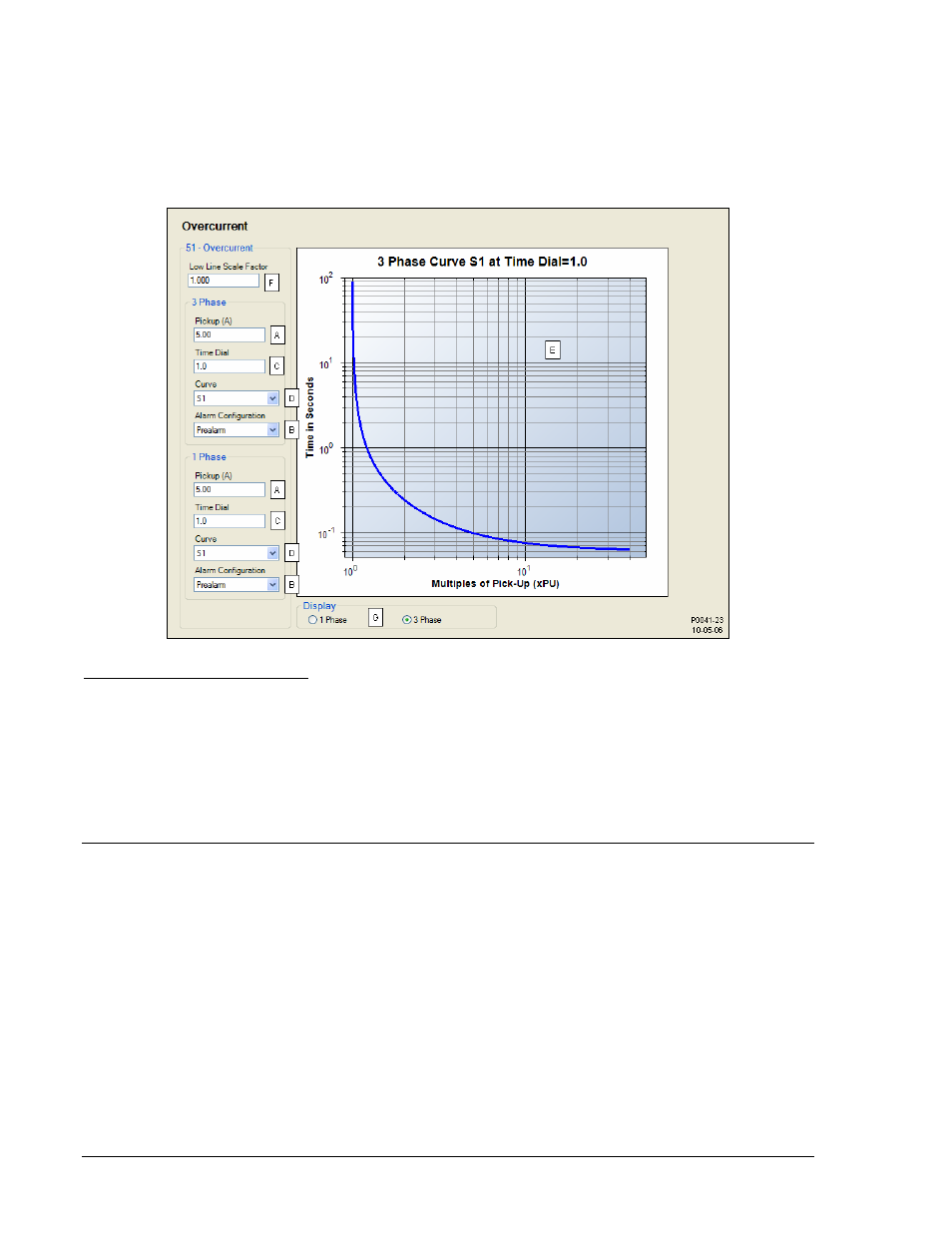
settings. For example, if a scale factor contact input is received by the DGC-2020 and the scale factor
setting is 2.000, the pickup setting will be doubled (2.000
× PU).
The graph can be set
to display the 1 Phase or 3 Phase curve as determined by the settings on the left
side of the chart.
BESTCOMSPlus overcurrent protection settings (DGC-2020, Generator Protection, Overcurrent) are
illustrated in Figure 4-26.
Figure 4-26. BESTCOMSPlus Overcurrent Protection Settings
A
Pickup: Adjustable from 0.9 to 7.75 Aac for 5 Aac current sensing (style number 5xxxxxxxx) or 0.18 to
1.18 Aac for 1 Aac current sensing (style number 1xxxxxxxx).
B
Alarm Configuration: None, Alarm, or Prealarm
C
Time Dial: Adjustable from 0 to 30 s for F (fixed) curve, 0 to 9.9 for all other curve selections.
D
Curve: A, B, C, D, E1, E2, F, G, I1, I2, L1, L2, M, S1, S2, V1, or V2.
E
Overcurrent Pickup Curve.
F
Low Line Scale Factor: Adjustable from 0 to 3.000 in 0.001 increments.
G
Display: 1 Phase or 3 Phase.
BREAKER MANAGEMENT
DGC-2020 breaker management features include the control of two, continuous- or pulse-controlled
breakers, load transfer upon detection of a mains failure, two modes of automatic genset synchronization,
and settings for stable or dead bus detection.
The description of breaker management is organized as follows:
• Breaker
Hardware
• Bus Condition Detection
• Synchronizer
Breaker Hardware
By default, one (generator) breaker is enabled
for control and monitoring by the DGC-2020. In
applications requiring control of a generator breaker and mains breaker, a second (mains) breaker can be
enabled
and configured.
When two breakers are configured (enabled), the DGC-2020 can be enabled to automatically transfer
load power from the mains to the genset during a mains failure
. This feature also enables the DGC-2020