Clearing the on-screen logic diagram, Bestlogic+ examples, Example 1 - avr logic block connections – Winco DGC-2020 User Manual
Page 109: Example 2 - and gate connections, Example 3 - multiple logic connections, Clearing the on-screen logic diagram -11, Example 1 - avr logic block connections -11, Figure 5-6. example 2 - and gate connections
9400200990 Rev B
DGC-2020 BESTlogic+ Programmable Logic
5-11
you would like to print. Next, the Print dialog box opens with the typical Windows
®
choice to setup the
properties of printer. Execute this command, as necessary, and then select Print.
A Page Setup icon is also provided on the BESTlogic+ Programmable Logic toolbar allowing you to select
Paper Size, Paper Source, Orientation, and Margins.
Clearing the On-Screen Logic Diagram
Click on the Clear button to clear the on-screen logic diagram and start over.
BESTlogic+ EXAMPLES
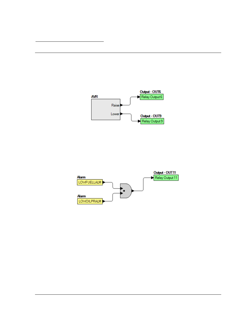
Example 1 - AVR Logic Block Connections
Figure 5-5 illustrates the AVR logic block and two output logic blocks. Output 6 is active while the AVR is
being raised and Output 9 is active while the AVR is being lowered.
Figure 5-5. Example 1 - AVR Logic Block Connections
Example 2 - AND Gate Connections
Figure 5-6 illustrates a typical AND gate connection. In this example, Output 11 will become active when
the Low Fuel alarm AND the Low Oil Pressure alarm are TRUE.
Figure 5-6. Example 2 - AND Gate Connections
Example 3 - Multiple Logic Connections
In this example, there are two comment boxes, which may be placed on the logic diagram. Double-click a
comment box to modify the inside text. Output 5 will become TRUE when the 27TRIP is TRUE. Output 7
will become TRUE when the Cool Temp Sender Fail is TRUE. Output 1 will become TRUE when the
DGC-2020 is in RUN mode (RUN Mode TRUE). Refer to Figure 5-7.