Winco DGC-2020 User Manual
Page 179
9400200990 Rev B
DGC-2020 Modbus
™ Communication
B-21
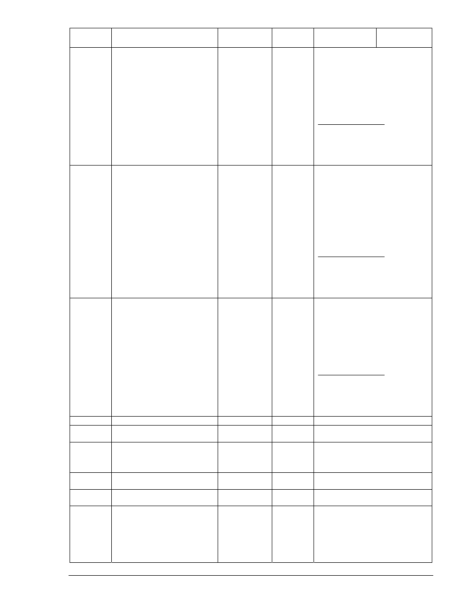
Holding
Register
Parameter Range
Read/Write
Supported
Data
Format
Units
40490
ECU Param. Status Group 8
R
bits 0-2: % engine torque at point 4
bits 3-5: engine speed at point 5
bits 6-8: % engine torque at point 5
bits 9-11: engine speed at high idle
point 6
bits 12-14: gain (Kp) of endspeed
governor
Bit 15: NOT USED
3-Bit Status Flag Values:
000 for Valid Data
001 for No Comms
010 for Not Sent
011 for Not Supp
100 for Sender Error
40491
ECU Param. Status Group 9
R
bits 0-2: reference engine torque
bits 3-5: max. momentary engine
override speed point 7
bits 6-8: max. momentary engine
override time limit
bits 9-11: requested speed control
range lower limit
bits 12-14: requested speed control
range upper limit
Bit 15: NOT USED
3-Bit Status Flag Values:
000 for Valid Data
001 for No Comms
010 for Not Sent
011 for Not Supp
100 for Sender Error
40492
ECU Param. Status Group 10
R
bits 0-2: requested torque control
range lower limit
bits 3-5: requested torque control
range upper limit
bits 6-8: not used
bits 9-11: not used
bits 12-14: not used
Bit 15: NOT USED
3-Bit Status Flag Values:
000 for Valid Data
001 for No Comms
010 for Not Sent
011 for Not Supp
100 for Sender Error
40493-99 FUTURE
USE
40500
DGC-2020 product series identifier
2020
R
40501
Firmware Part Number - 2nd most
significant digit. NOTE: The most
significant digit is always 9, but is
not mapped.
0 - 9
R
40502
Firmware Part Number - 3rd-6th
most significant digits
0000 - 9999
R
40503
Firmware Part Number - four least
significant digits
0000 - 9999
R
40504 LED
Status
individual bits
are 0 or 1
R
Bits indicate status of LED’s:
b0 = RUN
b1 = OFF
b2 = AUTO
b3 = ALARM
b4 = LOAD
b5 = NOT IN AUTO