Diagnostic trouble codes (dtcs) – Winco DGC-2020 User Manual
Page 42
3-6
DGC-2020 Functional Description
9400200990 Rev B
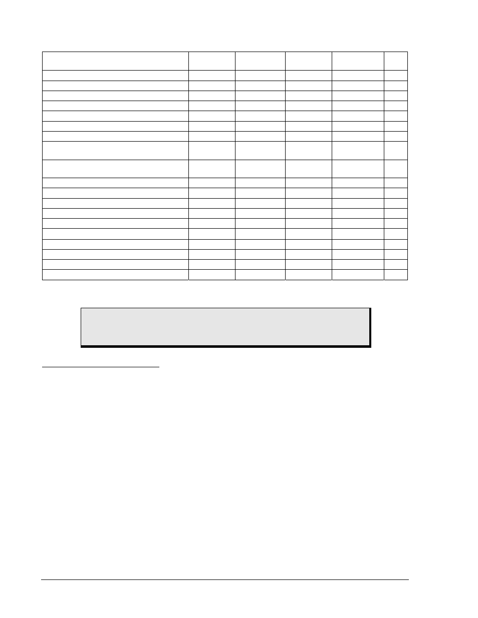
Table 3-2. Engine Configuration Parameters Obtained from CAN Interface
ECU Parameter
Metric
Units
English
Units
Update
Rate
Decimal
Place
∗
SPN
Engine speed at high idle point 6
rpm
rpm
5 s
none
532
Engine speed at idle point 1
rpm
rpm
5 s
none
188
Engine speed at point 2
rpm
rpm
5 s
none
528
Engine speed at point 3
rpm
rpm
5 s
none
529
Engine speed at point 4
rpm
rpm
5 s
none
530
Engine speed at point 5
rpm
rpm
5 s
none
531
Gain (Kp) of endspeed governor
%/rpm
%/rpm
5 s
100
th
545
Maximum momentary engine override
speed point 7
rpm rpm 5
s none
533
Maximum momentary engine override time
limit
seconds seconds
5
s
10
th
534
Percent torque at idle point 1
%
%
5 s
none
539
Percent torque at point 2
%
%
5 s
none
540
Percent torque at point 3
%
%
5 s
none
541
Percent torque at point 4
%
%
5 s
none
542
Percent torque at point 5
%
%
5 s
none
543
Reference engine torque
N
•m
ft-lb 5
s none
544
Requested speed control range lower limit
rpm
rpm
5 s
none
535
Requested speed control range upper limit
rpm
rpm
5 s
none
536
Requested torque control range lower limit
%
%
5 s
none
537
Requested torque control range upper limit
%
%
5 s
none
538
∗ SPN is suspect parameter number.
Diagnostic Trouble Codes (DTCs)
The DGC-2020 obtains diagnostic engine information from a compatible engine control unit (ECU). The
DGC-2020 will receive an unsolicited message of a currently active diagnostic trouble code (DTC).
Previously active DTCs are available upon request. Active and previously active DTCs can be cleared on
request. Table 3-3 lists the diagnostic information that the DGC-2020 obtains over the CAN interface.
DTCs are reported in coded diagnostic information that includes the Suspect Parameter Number (SPN),
Failure Mode Identifier (FMI), and Occurrence Count (OC). All parameters have an SPN and are used to
display or identify the items for which diagnostics are being reported. The FMI defines the type of failure
detected in the subsystem identified by an SPN. The reported problem may not be an electrical failure but
a subsystem condition needing to be reported to an operator or technician. The OC contains the number
of times that a fault has gone from active to previously active.
CAUTION
When the CAN interface is enabled, the DGC-2020 will ignore the following
sender inputs: oil pressure, coolant temperature, and magnetic pickup.