Rear panel, Figure 2-10. dgc-2020 rear panel hmi, Table 2-2. rear panel hmi descriptions – Winco DGC-2020 User Manual
Page 33
9400200990 Rev B
DGC-2020 Human-Machine Interface
2-11
REAR PANEL
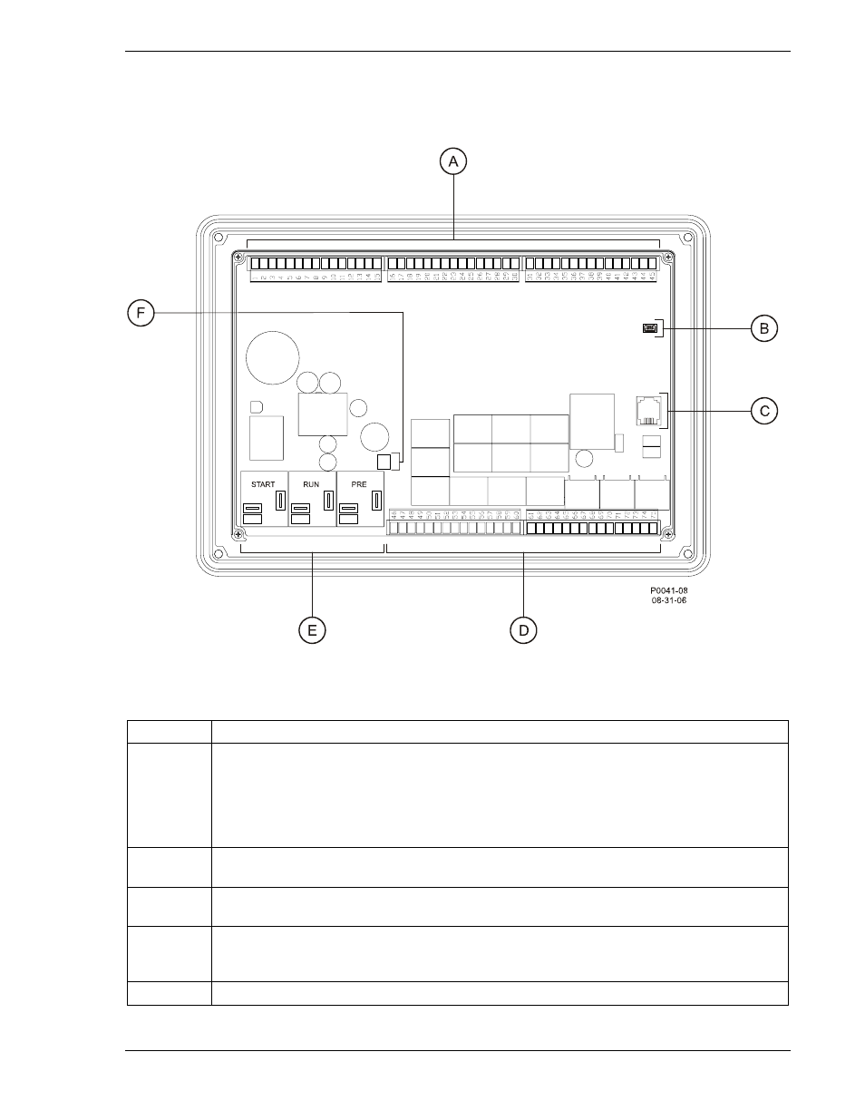
All DGC-2020 terminals and connectors are located on the rear panel. Rear panel terminals and
connectors are illustrated in Figure 2-10. (To show the terminals and connectors, Figure 2-10 shows the
DGC-2020 with the rear cover removed.) Table 2-2 lists the call-outs of Figure 2-10 along with a
description of each connector type.
Figure 2-10. DGC-2020 Rear Panel HMI
Table 2-2. Rear Panel HMI Descriptions
Locator Description
A, D
The majority of external, DGC-2020 wiring is terminated at 15-position connectors with
compression terminals. These connectors plug into headers on the DGC-2020. The
connectors and headers have a dovetailed edge that ensures proper connector
orientation. Each connector and header is uniquely keyed to ensure that a connector
mates only with the correct header. Connector screw terminals accept a maximum wire
size of 12 AWG.
B
The mini-B USB socket mates with a standard USB cable and is used with a PC running
BESTCOMSPlus software for local communication with the DGC-2020.
C
DGC-2020 controllers with an optional, internal, dial-out modem connect to a telephone
line through a USOC RJ-11 jack.
E
Connections to the DGC-2020 Start (starter), Run (fuel solenoid), and Pre (glow plug)
output contacts are made directly to each relay through quarter-inch, male, quick-connect
terminals.
F
An optional battery backup for the real-time clock is available when ordering.