Level diagrams, Analog input/output, Digital input/output – Toa D-2000 Series Installation User Manual
Page 70
70
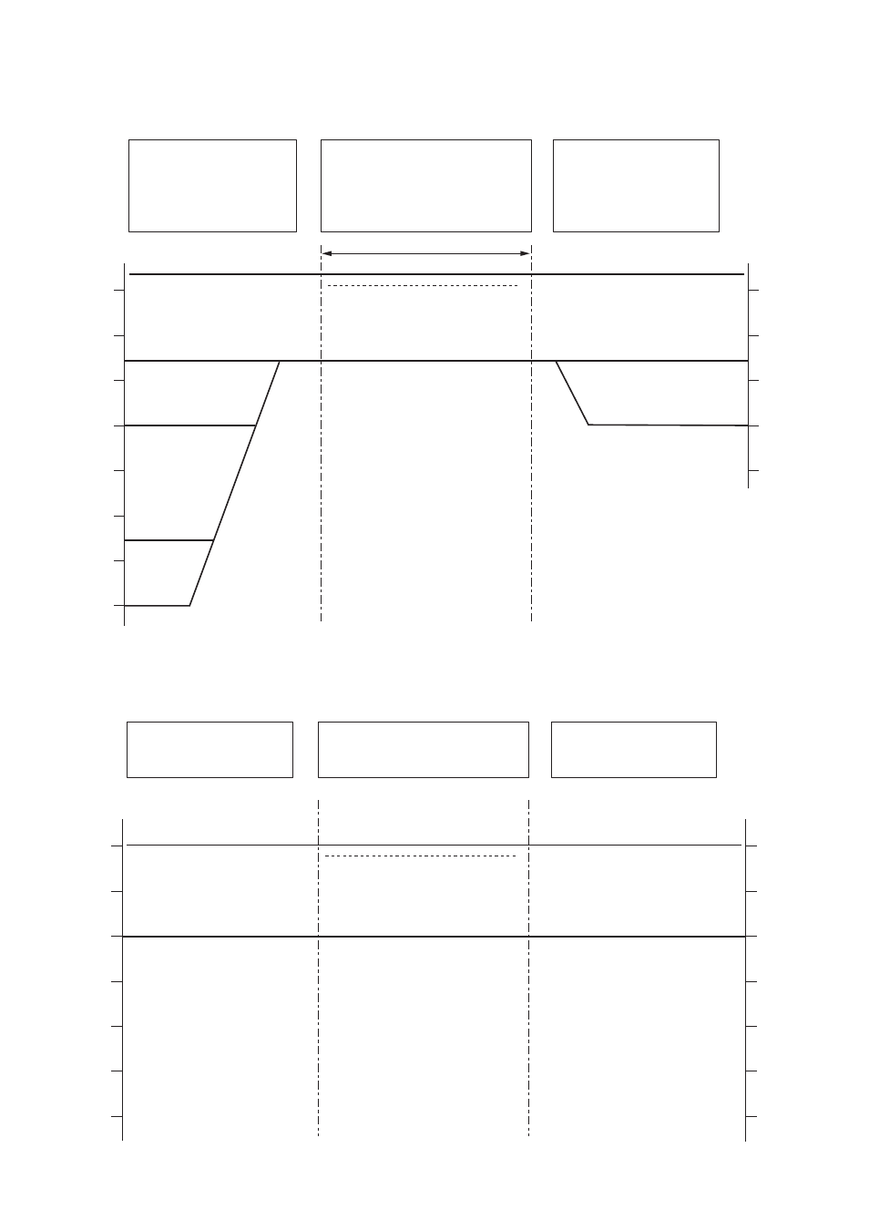
10. LEVEL DIAGRAMS
10.1. Analog Input/Output
Microphone/Line Input Module
D-921F, D-921E, D-922F,
D-922E, or D-2000AD1,
or
Stereo Input Module D-936R
DSP
Line Output Module
D-971M, D-971E, D-971R,
or D-2000DA1
dBu
+20
+10
0
-10
-20
-30
-40
-50
dBu
+20
+10
0
-10
-20
LINE
(+4)
LINE
(-10)
MIC
(-36)
MIC
(-50)
Peak LED Turns ON
(+17 dB)
(0 dB)
Max. Input (+24)
Digital
Clipping Level (+20 dB)
(+4) D-971M/E, D-2000DA1*
1
When the output level is set to "+4 dB."
*
1
When the output level is set to "–10 dB."
*
2
(–10) D-971R, D-2000DA1*
2
10.2. Digital Input/Output
Digital Input Module
D-923AE or D-937SP
DSP
Digital Output Module
D-972AE or D-961SP
dBFS
0
-20
-40
-60
0
-20
-40
-60
dBFS
Peak LED Turns ON
(+17 dB)
(0 dB)
Max. Input (0 dBFS)
Clipping Level (+20 dB)
This manual is related to the following products: