Caution – Toa D-2000 Series Installation User Manual
Page 28
28
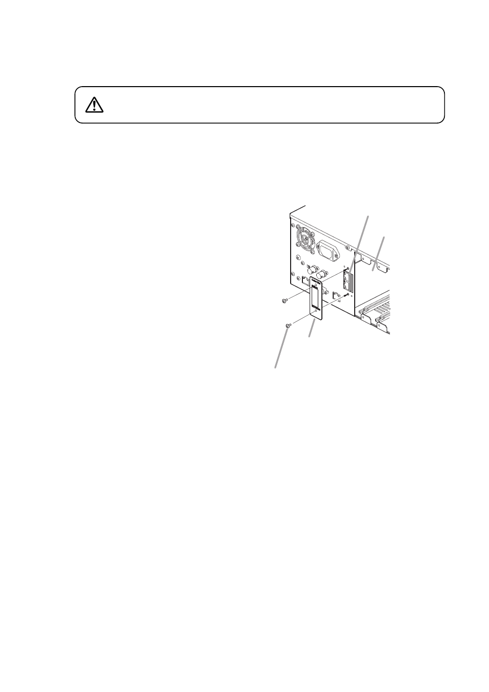
Step 7. Secure the panel to the CobraNet interface
module slot section with 2 screws.
Ensure that 2 connectors of the D-2000CB
project from the rectangle hole in the panel
before tightening screws.
[Installing the input, output, and control modules]
After mounting completion of the D-2000CB, install
other modules with the removed screws that held the
blank panels.
Further, replace the removed blank panels to the idle
slots.
D-2008SP
D-2000CB
D-2000CB's connector
Panel
(removed in step 4)
7
Machine screw M3 x 8
(removed in step 4)
Terminal pins of the connector are exposed on the solder side of
the D-2000CB board. Never touch these terminal pins when
inserting the connector to prevent finger injury.
CAUTION
Step 6. Secure the D-2000CB to the inside of the D-2008SP with 1 screw.
Note
Be sure to secure the D-2000CB with the screw.
Doing otherwise may cause its connector to be disconnected, resulting in malfunction.
Step 4. Remove the D-2000CB's panel.
Note: The removed 2 screws are used in step 7.
Step 5. Insert the D-2000CB's connector into the D-2008SP's internal connector.