Electrical supply and connections, Control thermostat – Reznor SCE Unit Installation Manual User Manual
Page 20
Form RZ-NA I-SCE, Page 20
11. Electrical Supply
and Connections
All electrical wiring and connections including electrical grounding must be made in accor-
dance with the National Electric Code ANSI/NFPA No. 70 (latest edition) .
Check any local ordinances or gas company requirements that apply.
Check the rating plate on the heater for the supply voltage and the current requirements. A
separate line voltage supply with fused disconnect switch should be run directly from the
main electrical panel to the unit, making connections in the junction box. Refer to
FIGURE 1,
Paragraph 3. Seal all electrical entrance openings with field-supplied bushings.
A disconnect switch is available as optional equipment or may be supplied locally. When
installing the disconnect switch, be careful that the conduit and switch housing are clear of
all service panels. Allow at least four feet (1.2M) of service room between the disconnect
switch and any removable service panels. When providing or replacing fuses in a fusible
disconnect switch, use dual element time delay fuses and size 1.25 times the maximum total
input amps.
The heater is equipped with a low voltage (24V) control circuit. See the typical wiring dia-
grams on pages 21 and 22; a specific wiring diagram can be found in the heater junction box.
See separate instruction sheets for any optional equipment provided. Optional equipment is
identified on the wiring diagram supplied with the heater.
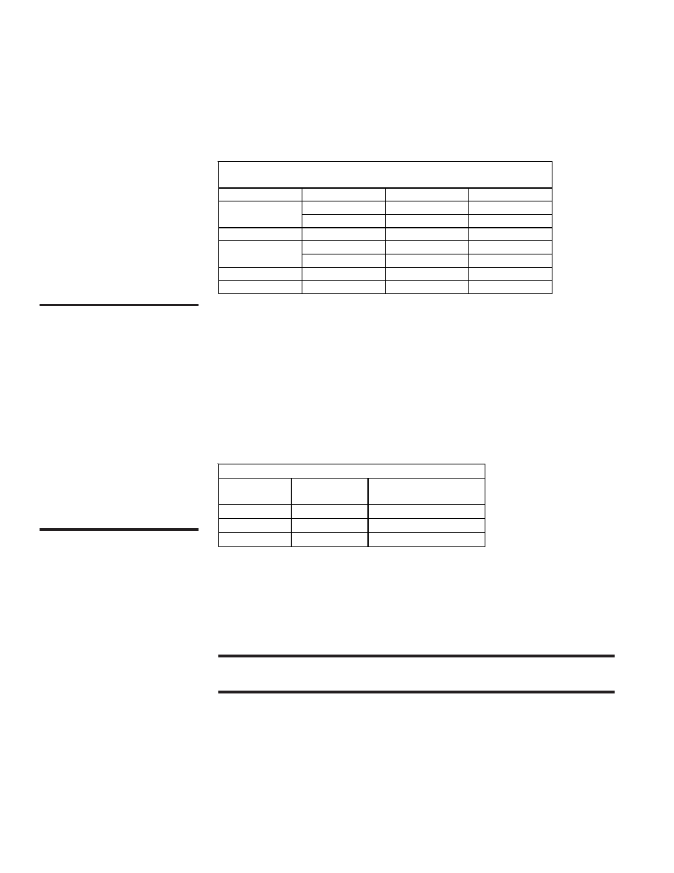
Field Control Wiring - Length and Gauge
Total Wire
Length
Distance from
Unit to Control
Minimum Recommended
Wire Gauge
150ft (46M)
75ft (23M)
#18 gauge
250ft (76M)
125ft (38M)
#16 gauge
350ft (107M)
175ft (53M)
#14 gauge
CAUTION: If any of the
original wire as supplied
with the appliance must be
replaced, it must be
replaced with wiring
material having a
temperature rating of at
least 105°C, except for
sensor lead and optional
bypass damper combustion
air safety circuit (Option
AG39 or AG40) wires
which must be 150°C. See
Hazard Levels, page 2.
Voltage/Phase
Motor HP
Wire Gauge
BX Cable
120/1
1/4 - 1/2
14
3/8"
1
12
3/8"
208-230/1
1 - 1-1/2
14
3/8"
208-230/3
1/4 - 3
14
3/8"
5
12
3/8"
460/3
1/4 - 5
14
3/8"
575/3
1/2 - 5
14
3/8"
Field-Supplied Wiring Size from Disconnect to Electrical Box for
Connection to Motor Contactor or Starter
12. Control
Thermostat
A thermostat is not supplied with the furnace. Use either an optional or a field-provided low-
voltage (24V) thermostat. Install the thermostat according to the manufacturer's instruc-
tions.
A low voltage thermostat is equipped with a heat anticipator which levels out unit cycling for
optimum temperature control. Set the anticipator at 1.0 amps for standard controls. See chart
below for amp ratings of optional controls.
CAUTION: Control circuit amps should be within the anticipator amp
rating of the thermostat used.
Ampere Rating of 24-Volt Controls
Fan Control ...............................
.12 amps
Time Delay Heater .....................
.14 amps
RBM Relay Coil .........................
.12 amps
Contactor Coil ...........................
.45 amps
Spark Ignition System............... .1 amps
Maxitrol Gas Control System .... .51 amps
Honeywell Gas Valve ................ .5 amps
White-Rodgers Gas Valve .. ....... .6 amps