Horizontal vent instructions (cont’d) – Reznor SCE Unit Installation Manual User Manual
Page 14
Form RZ-NA I-SCE, Page 14
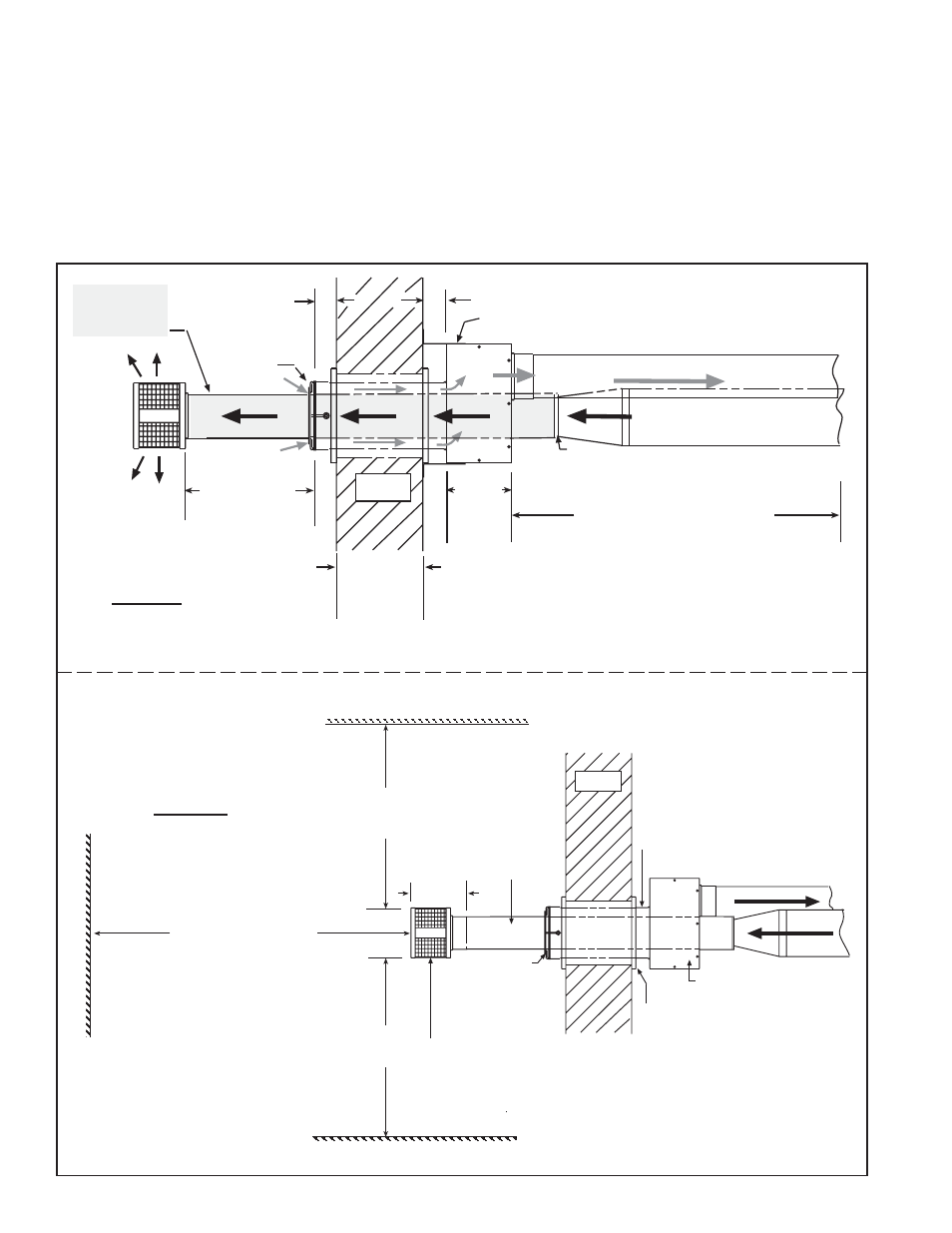
6-15/16 (176mm)
Concentric
Adapter Box
Double-Wall
Vent Pipe -
Pitch to
Drain
Thimble
Combustion Air Pipe -
Pitch to Drain
3 ft (1M)
minimum
3 ft (1M)
minimum
6 ft (1.8M) minimum
Adjoining Building
Building Projection
Building Overhang
W a l l
Inlet Air
Guard
Exhaust (Vent) Cap
IMPORTANT: Install exhaust cap so the baffles
are positioned at 12:00, 3:00, 6:00, and 9:00 oclock.
Side View
16 (406mm)
minimum
24 (610mm)
maximum
Concentric
Adapter
Box
Wall
Screened
Exhaust
Cap
Inlet Air
Guard
Combustion Air to heater (seal joints)
Vent (Flue Exhaust) Pipe
from heater (seal joints)
Heater
Distance between the
Concentric Adapter Box
and the Heater
For Maximum Length,
see Table on page 8.
Minimum length is 5 ft (1.5M).
Attach double-vent pipe to vent run no
more than 6 (152mm) from the box. A
taper-type reducer is required.
2 (51mm) if wall is combustible
Attach box to wall with brackets.
One piece of
Double-Wall
Vent Pipe
2 (51mm)
6
(152
mm)
1 (25mm)
minimum
48
(1219mm)
maximum
Top View
FIGURE 13 - Installation
of a Typical Separated-
Combustion Unit with
Horizontal Vent and
Combustion Air Pipes
(Option CC6)
completely.
10. Attach the indoor combustion air pipe. If using 6" pipes, attach the single-wall combus-
tion air pipe run to the collar on the concentric adapter box with sheetmetal screws. If using
7” pipe on Sizes 200-400, install a taper type enlarger as illustrated In FIGURE 11, page 11.
Seal joints with tape or sealant.
Installation of the horizontal vent and combustion air system on your separated-combus-
tion unit is complete. Verify compliance with all venting installation requirements, pages
8-11, and FIGURE 13.
HORIZONTAL VENT
INSTRUCTIONS
(cont’d)