Reznor CAUA Unit Installation Manual User Manual
Page 9
Form I-CAUA, P/N 164771 R8, Page 9
Installation should be done by a qualified agency in accordance with these instruc-
tions. The qualified service agency installing the vent or vent/combustion air system is
responsible for the installation.
The venting or venting/combustion air systems illustrated in this manual are the only
ones approved for a Model CAUA heater.
Decide which Venting
System to Install:
Separated-Combustion -
A separated-combustion installation
requires a vent/
combustion air system that uses a power venter to
duct combustion air from out-
doors and exhaust flue products to the outdoors. A vent/combustion air kit, Option
CC2 or CC6, is required. Follow the instructions in Paragraph 6.2.1 beginning below.
Power-Vented -
A power-vented installation uses a power venter to draw
com-
bustion air from the indoor space and exhaust flue products to the outdoors. A vent
cap, Option CC1 or equivalent, is required. Follow the instructions in Paragraph 6.2.2,
beginning on page 20.
A minimum length of 12"
(305mm) of straight pipe
is
always required at
the venter outlet.
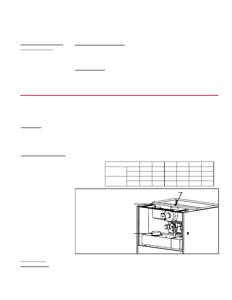
FIGURE 3 - Venter
Outlet and Combustion
Air Pipe Collars
Venter Outlet - 5 Sizes 150, 200, 250; 6 Sizes 300, 350,
400 -- 12 (305mm) of straight pipe is required at the outlet.
Use tin snips to cut
out the hole for the
combustion air pipe.
Collar for connecting
combustion air pipe
5 Sizes 150, 200;
6 Sizes 250, 300,
350, 400.
2) Venter Outlet and
Combustion Air
Inlet
6.2.1. Venting and Combustion Air Requirements for a Separated Combustion Installation
(must use either Option CC2 or CC6)
All pipe is field supplied. Requirements are listed for both vent pipe and combustion
air inlet pipe.
Vent Pipe
1) Type of Pipe
• Vent pipe approved for a Category III appliance
OR single-wall, 26-gauge or
heavier galvanized (or a material of equivalent durability and corrosion resistance)
vent pipe is
required between the heater and the concentric adapter box.
• Double-wall (Type B) vent pipe is
required for the vent terminal section. The length
of pipe that extends through the box and runs concentric through the combustion
air pipe
must be one-piece with no joints.
• Sealed, single-wall galvanized combustion air pipe is recommended.
Combustion Air Pipe
TABLE 6 -
Venter and
Inlet Collar
Sizes
Use tin snips or aviation shears to cut out the hole in the top of the heater (See
FIG-
URE 3). Insert the pipe down through the hole and attach it to the collar inside the
heater. Seal the joint. (Larger size heaters have oval collars. If the collar is oval, form
the pipe to fit the collar.)
Combustion
Air Inlet Collar
Size
150
200
250
300
350
400
Venter
Outlet
inches
5
5
5
6
6
6
mm
127
127
127
152
152
152
Combustion
Air Inlet
inches
5
5
6
6
6
6
mm
127
127
152
152
152
152