Reznor CAUA Unit Installation Manual User Manual
Page 23
Form I-CAUA, P/N 164771 R8, Page 23
Horizontal Vent
Terminal Clearances
A vent cap is required. Maintain a clearance of 12" (305mm) from the wall to the vent
terminal cap for stability under wind conditions.
Products of combustion can cause discoloration of some building finishes and dete-
rioration of masonry materials. Applying a clear silicone sealant that is normally used
to protect concrete driveways can protect masonry materials. If discoloration is an
esthetic problem, relocate the vent or install a vertical vent.
TABLE 14 - Horizontal
Vent Clearances
Structure
Minimum Clearances for Vent Terminal Location (all directions
unless specified)
Forced air inlet within 10 ft (3.1M)*
3 ft (0.9M) above
Combustion air inlet of another appliance
6 ft (1.8M)
Door, window, or gravity air inlet (any building opening)
4 ft (1.2M) horizontally; 4 ft (1.2M) below; 1 ft (305mm) above
Electric meter, gas meter ** and relief equipment
U.S. - 4 ft (1.2M) horizontally; Canada - 6 ft (1.8M)
Gas regulator **
U.S. - 3 ft (0.9M); Canada - 6 ft (1.8M) horizontally
Adjoining building or parapet
6 ft (1.8M)
Adjacent public walkways
7 ft (2.1M) above
Grade (ground level)
3 ft (.9M) above***
*Does not apply to the inlet of a direct vent appliance. **Do not terminate the vent directly above a gas meter or service regulator.
*** Consider local snow depth conditions. The vent must be at least 6” (152mm) higher than anticipated snow depth.
Single-Wall Vent Run
and Double-Wall
Terminal
NOTE: Drawing is not
proportional; read all
measurements.
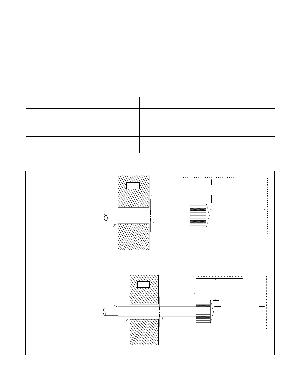
FIGURE 17 - Horizontal
Vent Terminals
Single-Wall Vent Run and
Single-Wall Terminal
A clearance thimble is required when flue pipe extends through combustible
materials. Follow the instructions of the thimble or vent pipe manufacturer.
Pitch flue pipe down toward
outlet 1/4 per foot for condensate drainage.
(NOTE: Slope applies to entire horizontal vent run.)
12
(305 mm)
minimum
Wall
Roof or Building Overhang
3 ft (1M)
minimum
6 ft (1.8M) minimum
Reznor (Option CC1) -
note positions of vent cap
openings (shaded areas)
Parapet or
Adjoining Building
NOTE: Drawing is not
proportional; read all
measurements.
A clearance thimble is required when flue pipe extends through combustible
materials. Follow the requirements of the thimble or pipe manufacturer.
Pitch flue pipe down toward
outlet 1/4 per foot for condensate drainage.
(NOTE: Slope applies to entire horizontal vent run.)
12
(305 mm)
minimum
Wall
Roof or Building Overhang
3 ft (1M)
minimum
6 ft (1.8M) minimum
Reznor (Option CC1) -
note positions of vent cap
openings (shaded areas)
Parapet or
Adjoining Building
Double-Wall
Vent Pipe*
*Follow the illustrated instructions in FIGURES 16B
and 16C to join the double-wall vent terminal section
to a single-wall vent run and to the vent cap.
6 (152mm) minimum
available with the heater (Option CC1) is recommended. A different style vent cap
could cause nuisance problems or unsafe conditions.
See the illustrations in
FIGURES 17 and 18 for requirements of vertical and horizontal
vent termination. The vent terminal pipe may be either single-wall or double-wall (Type
B). If double-wall pipe is used in the vent terminal with a single-wall vent run, follow the
illustrated instructions in
FIGURES 16B and 16C to attach the vent cap and to connect
the double-wall pipe to the single-wall vent pipe run.