2 thermostat and connections, Table 26- motor amps – Reznor CAUA Unit Installation Manual User Manual
Page 35
Form I-CAUA, P/N 164771 R8, Page 35
TABLE 26- Motor Amps
Full Load Amps (per motor) - Blower Motors
HP
1/3
1/2
3/4
1
1-1/2
2
3
5
Direct Drive Motors
208/230V 1 PH
--
--
--
6.3
--
--
--
--
Optional Belt Drive OPEN Motor
208V 1PH
3.0
5.1
5.5
7.5
7.8
12.3
13.7
28.0
230V 1PH
3.0
4.4
5.4
6.5
7.5
12.3
12.4
26.0
208V 3PH
1.9
2.5
2.9
3.4
5.6
7.0
9.0
13.4
230V 3PH
1.6
3.0
2.6
3.7
5.0
6.6
8.6
13.2
480V 3PH
0.8
1.5
1.3
2.0
2.8
3.5
4.3
6.6
575V 3PH
--
0.9
1.0
1.4
2.0
2.6
3.6
5.4
Optional Belt Drive TEFC Motor
208V 1PH
2.3
3.5
5.4
6.2
9.5
--
--
--
230V 1PH
2.4
3.6
5.5
6.0
8.2
8.3
15.0
20.2
208V 3PH
1.2
2.3
2.0
3.3
4.8
6.1
7.7
12.6
230V 3PH
1.2
2.0
2.2
3.1
4.6
5.6
7.0
11.4
480V 3PH
0.6
1.0
1.1
1.6
2.3
2.8
3.5
5.7
575V 3PH
--
0.7
0.8
1.4
1.7
2.2
2.9
4.7
CAUTION: An
external duct
system static
pressure not within
the limits shown
on the rating plate,
or improper motor
pulley or belt
adjustment, may
overload the motor
or cause the limit
control to activate.
See Hazard Levels,
page 2.
The electrical supply and control wiring enter at the top of the heater (See
FIGURE 1,
page 5) and connect to the supply voltage terminal strip located above the contactor(s)
or starter(s) (See
FIGURE 28).
Consult the wiring diagram supplied with your heater.
CAUTION: If any of the original wire as supplied with the appliance must be replaced,
it must be replaced with wiring material having a temperature rating of at least 105°C,
except for sensor lead wires which must be 150°C. See Hazard Levels, page 2.
The amps listed in
TABLE 26 can be used for sizing line wiring but should not be inter-
preted as the exact motor amps. See the motor rating plate for exact motor specifica-
tions. At final adjustment, amperes should not exceed motor nameplate amp rating.
The installation must be adjusted to obtain a temperature rise within the range speci-
fied on the heater rating plate.
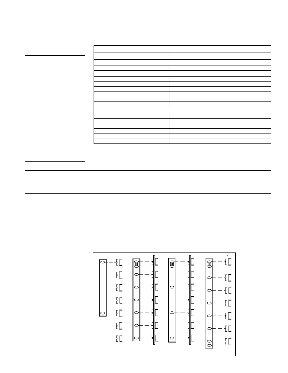
7.2 Thermostat and
Connections
A thermostat is not standard equipment but is an installation requirement. Use either
an optional thermostat available with the heater or a field-supplied 24-volt thermostat.
Install according to the thermostat manufacturer's instructions. Control wiring enters
on the right side of the heater and connects to the terminal strip in the control compart-
ment; see
FIGURE 30, page 38.
Make sure that the heat anticipator setting on the thermostat is in accordance with the
amperage value noted on the wiring diagram of your heater.
For cooling unit connections, refer to the wiring diagram or the cased cooling coil instal-
lation instructions, Form I-CAUA-CC. Follow the thermostat manufacturer's instruc-
tions.
TWO ST
AGE HEA
T/COOL
THERMOST
AT W/F
AN SWITCH
G
W1
W2
Y2
Y1
RC
RH
G
W
Y
R
RC
RH
AUX
G
W2
W1
Y2
Y1
X
RC
G
W2
W1
Y2
Y1
C
R
TERMINAL
STRIP
G
W1
W2
Y2
Y1
C
TERMINAL
STRIP
R
G
W1
W2
Y2
Y1
C
R
TERMINAL
STRIP
CL33
CL52
CL22
SINGLE ST
AGE THERMOST
AT
TERMINAL STRIP
G
W2
W
W1
Y2
Y1
C
R
R
CL1
SINGLE ST
AGE PROGRAMMABLE THERMOST
AT
TWO ST
AGE PROGRAMMABLE THERMOST
AT
C
FIGURE 29A -
Wiring Connections
for Option CL1, CL22,
CL52, and CL33
Thermostats