8 flue wrapper condensate drain, 0 electrical and wiring, 1 wiring – Reznor CAUA Unit Installation Manual User Manual
Page 34: 0 mechanical (cont'd), 7 burner condensate drain (cont'd)
Form I-CAUA, P/N 164771 R8, Page 34
3
4
2
1
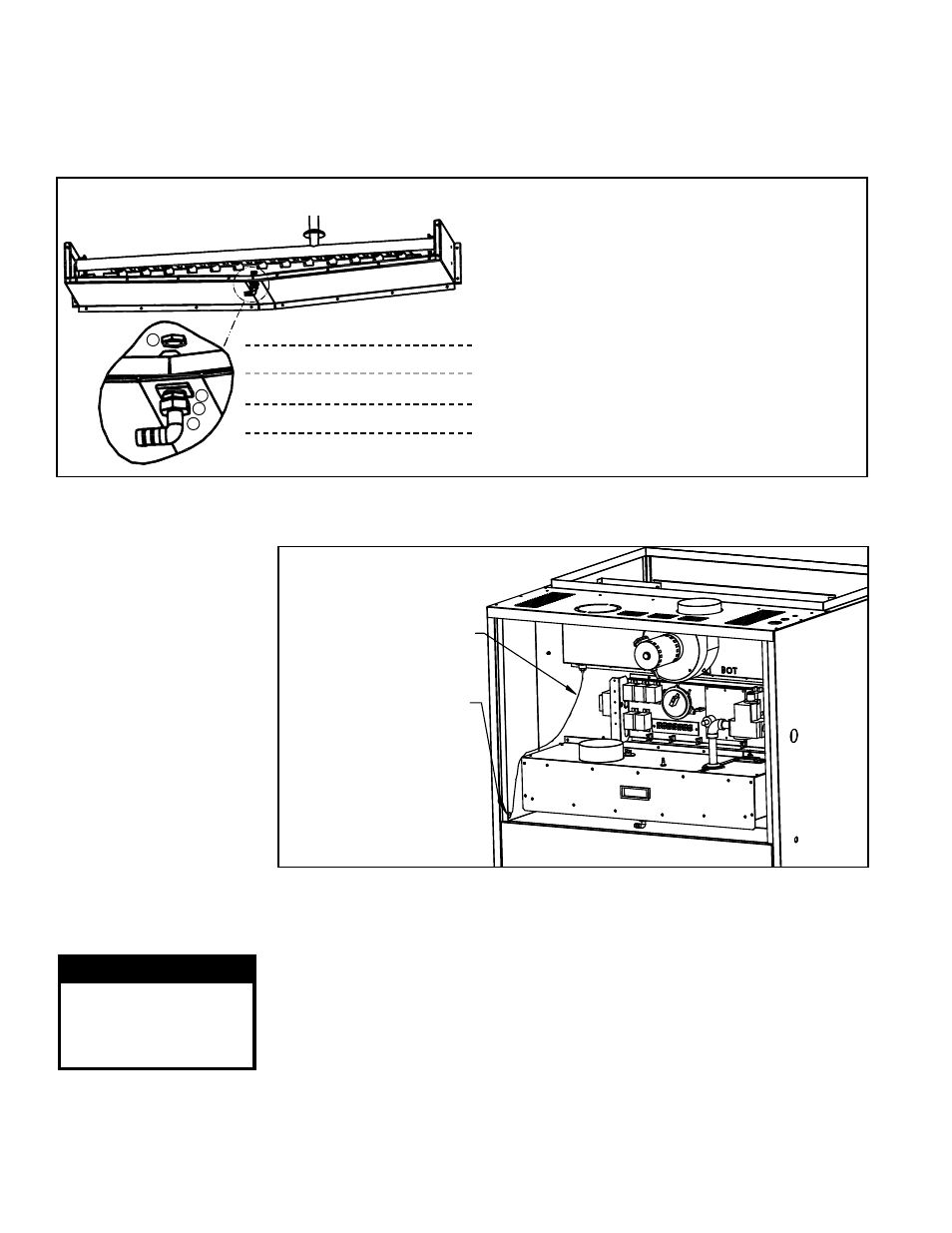
a) Assemble the brass nut, the sealing washer, and
the 90° fitting.
b) Position the threaded fitting up through the hole
so that the hose barb is toward the bushing in the
side of the cabinet. Attach using the silver-colored
locknut.
c) Under the burner, push the tubing onto the hose
barb, being sure that it is secure. Maintaining a
downward slope, extend the hose out through the
cabinet side.
d) Just after exiting the cabinet,
create a trap in the
line by making a loop in the hose. Secure the
loop with the wire ties.
e) Continue downward with the tubing, connecting it
into the coil drain pipe.
FIGURE 27 - Burner Condensate Drain
Connection
Hex Locknut (silver)
—Burner Bottom Pan—
Sealing Washer
Brass Nut
90° Nylon Fitting
6.0 Mechanical
(cont'd)
6.8 Flue Wrapper
Condensate
Drain
If equipped with a makeup air option to allow inlet air less than 35°F (Option AD4), the
flue wrapper will have a condensate drain. Follow the instructions in
FIGURE 28. Peri-
odic cleaning of the condensate drain is required.
FIGURE 28 - Unit with
Option AD4 which
includes a Condensate
Drain on the Flue
Wrapper
Condensate Drain
Tubing from Flue
Wrapper
Tubing exits through an
opening in side panel.
Connect it into either
the burner or coil
drain or directly
into a sanitary drain.
Periodic cleaning of
the condensate drain
is required.
Flue
Wrapper
6.7 Burner Condensate Drain (cont'd)
7.0 Electrical and
Wiring
All electrical wiring and connections, including electrical grounding, MUST be made
in accordance with the National Electric Code ANSI/NFPA No. 70 (latest edition) or,
in Canada, the Canadian Electrical Code, Part I-C.S.A. Standard C22.1. In addition,
the installer should be aware of and comply with any local ordinances or gas company
requirements.
7.1 Wiring
Check the rating plate on the heater for the supply voltage and current requirements.
A separate line voltage supply with fused disconnect switch should be run directly from
the main electrical panel to the heater. All external wiring must be within approved con-
duit and have a minimum temperature rise rating of 60°C. Conduit from the disconnect
switch must be run so as not to interfere with the service panels of the heater.
Use an amp meter to check motor amps.
TABLE 26 lists full load amps for all HP's
and voltages. Amps may be adjusted downward by reducing blower RPM or increasing
duct system static pressure.
WARNING
If you turn off the
power supply, turn off
the gas. See Hazard
Levels, page 2.
Motor Amps
4. Locate the hole in the bottom center of the burner pan and remove the plug.
Follow the instructions in
FIGURE 27 to install the drain. Complete all steps
as listed in the illustration. When installation of the burner condensate drain is
complete, re-assemble the heater.
Instructions for Installing Burner Condensate Drain (cont'd)