0 mechanical (cont'd), 2 venting and combustion air (cont'd) – Reznor CAUA Unit Installation Manual User Manual
Page 16
Form I-CAUA, P/N 164771 R8, Page 16
6-15/16 (176mm)
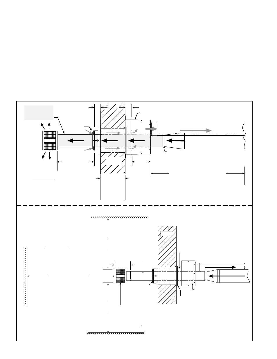
Concentric Adapter Box
Double-Wall
Vent Pipe -
Pitch to
Drain
Thimble
Combustion Air Pipe - Pitch to Drain
3 ft (1M)
minimum
3 ft (1M)
minimum
6 ft (1.8M) minimum
Adjoining Building
Building Projection
Building Overhang
W a l l
Inlet Air
Guard
Exhaust (Vent) Cap
IMPORTANT: Install exhaust cap so the baffles
are positioned at 12:00, 3:00, 6:00, and 9:00 oclock.
Side View
16 (406mm)
minimum
24 (610mm)
maximum
Concentric
Adapter
Box
Wall
Screened
Exhaust
Cap
Inlet Air
Guard
Combustion Air to heater (seal joints)
Vent (Flue Exhaust) Pipe
from heater (seal joints)
Heater
Distance between the
Concentric Adapter Box
and the Heater
For Maximum Length,
see Table on page 10.
Minimum length is 5 ft (1.5M).
Attach double-vent pipe to vent run no
more than 6 (152mm) from the box. A
taper-type reducer is required on Sizes
150, 200, 300, 350, and 400.
2 (51mm) if wall is combustible
Attach box to wall with brackets.
One piece of
Double-Wall
Vent Pipe
2 (51mm)
6
(152
mm)
1 (25mm)
minimum
48
(1219mm)
maximum
Top View
FIGURE 8 - Installation
of a Typical Separated-
Combustion Unit with
Horizontal Vent and
Combustion Air Pipes
(Option CC6)
9) Seal the vent pipe. Verify that the double-wall section of vent pipe has a slight
downward drop (1/4" per foot/6mm per 305mm) toward the vent terminal end. Use
silicone sealant and seal the circumference of the pipe and the opening of the box.
Seal the area around the pipe completely.
10) Attach the indoor combustion air pipe. On Sizes 150 and 200, install a taper-
type enlarger as illustrated in
FIGURE 4A, page 11. On Sizes 250, 300, 350, and
400, attach the single-wall combustion air pipe run to the collar on the concentric
adapter box with sheetmetal screws. Seal joints with tape or sealant.
Installation of the horizontal vent and combustion air system on your separated com-
bustion unit is complete. Verify compliance with all venting installation requirements,
pages 9-13, and
FIGURE 8.
6.0 Mechanical
(cont'd)
6.2 Venting and
Combustion Air
(cont'd)
6.2.1 Venting and Combustion Air Requirements for a Separated
Combustion (cont'd)
6.2.1.1 HORIZONTAL Vent Instructions (cont'd)