1 filter cabinet, option cw (return air only) – Reznor CAUA Unit Installation Manual User Manual
Page 25
Form I-CAUA, P/N 164771 R8, Page 25
6.3.1 Filter Cabinet,
Option CW (return air
only)
A side or rear filter cabinet designed for 2" pleated disposable or permanent metal
filters is shipped separately for field assembly and installation. A bottom filter cabinet is
factory assembled and is available with 2" disposable filters in addition to the pleated
or permanent filters. Depending on the option selected, filters are either shipped with
the cabinet or are field-supplied.
To adapt to a variety of applications, the heater cabinet is designed so that the filter
cabinet can be positioned on either the right side, the left side, the rear, or the bottom of
the heater. The larger filter cabinets (
FIGURES 19B and 19C) are uniquely designed
so that the same cabinet can be field-assembled and installed with either a horizontal
or vertical air inlet. The smaller filter cabinet in
FIGURE 19A is limited to Sizes 150 and
200 and is available with a horizontal inlet only. The bottom filter cabinet
FIGURE 19D
allows air to enter from below the heater. All cabinets have door panels for easy filter
removal for changing or cleaning.
All of the filter cabinets have a duct flange for attaching the inlet air duct. For inlet duct
dimensions, see
TABLE 15.
Follow the installation instructions included with the filter cabinet package.
Filter Cabinet NOTES
(apply to FIGURES 19A,
19B, 19C, and 19D:
* Requires 2" permanent
filters.
** If using side inlets, two
cabinets must be installed,
one on each side.
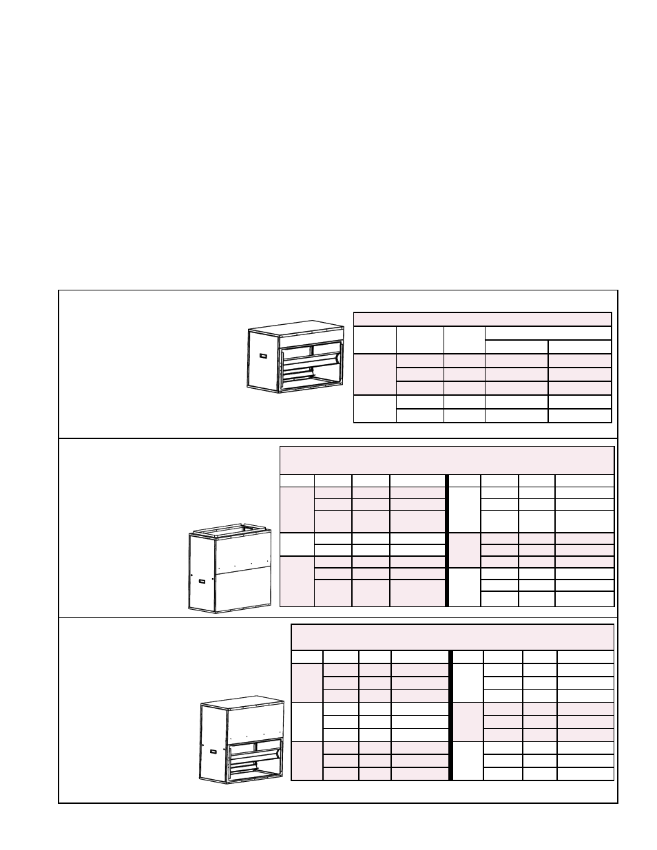
FIGURES 19A-19D - Filter Cabinets with Filter Arrangements and Filter Sizes
TABLE 16 - Filters for Options CW8, CW9, CW10
CAUA
Size
CFM
FPM
2" Filters
Pleated
Permanent
150
1800
375
(2) 12 x 32
(4) 12 x 16
2400
500
(2) 12 x 32
(4) 12 x 16
*3000
625
--
(4) 12 x 16
200
2400
500
(2) 12 x 32
(4) 12 x 16
*3000
625
--
(4) 12 x 16
FIGURE 19A - Small Filter Cabinet for Sizes 150 and 200 only -- Horizontal Air Inlet Only
Option CW8 with 2" Pleated Filters
Option CW9 with 2" Permanent
Filters
Option CW10 for Field-Supplied
Filters
*Requires permanent filters.
Opt CW4 w/2" Pleated Filters
Opt CW5 w/2" Permanent Filters
Opt CW6 for Field-Supplied Filters
FIGURE 19B - Assembled with
Vertical Air Inlet Opening
TABLE 17 - Sizes of Permanent or Pleated 2" Filters for Options
CW4, CW5, or CW6
Size CFM FPM
Filters
Size CFM FPM
Filters
150
1800
281
(4) 16 x 16
300
3000
469
(4) 16 x 16
2400
375
(4) 16 x 16
*4000
625
(4) 16 x 16
3000
469
(4) 16 x 16
**5000
781
(4) 16 x 16
(4) 16 x 16
200
2400
375
(4) 16 x 16
350
4300
448
(6) 16 x 16
3000
469
(4) 16 x 16
5000
521
(6) 16 x 16
250
3000
469
(4) 16 x 16
*6000
625
(6) 16 x 16
*4000
625
(4) 16 x 16
400
4300
448
(6) 16 x 16
**5000
781
(4) 16 x 16
(4) 16 x 16
5000
521
(6) 16 x 16
*6000
625
(6) 16 x 16
• Attaches on Either
Side of the Heater
• Vertical (Top) or
Horizontal Inlet
Opening
• "V" Filter Rack
Arrangement
• Horizontal Inlet Opening
• "V" Filter Rack Arrangement
• Attaches on either Side or the Rear of a Size 150
or 200 Heater
FIGURE 19C - Assembled with
Horizontal Air Inlet Opening
Opt CW7 w/2" Pleated Filters
Opt CW12 w/2" Permanent Filters
Opt CW11 for Field-Supplied Filters
* Requires permanent filters. **If filter cabinet attaches to heater side (CW 4,5,6), install 2 cabinets (1 on each side).
TABLE 18 - Sizes of Permanent or Pleated 2" Filters for
Options CW7, CW12, or CW11
Size
CFM
FPM
Filters
Size
CFM
FPM
Filters
150
1800
281
(4) 16 x 16
300
3000
313
(6) 16 x 16
2400
375
(4) 16 x 16
4000
417
(6) 16 x 16
3000
469
(4) 16 x 16
5000
521
(6) 16 x 16
200
2400
375
(4) 16 x 16
350
4300
448
(6) 16 x 16
3000
469
(4) 16 x 16
5000
521
(6) 16 x 16
-
-
-
*6000
625
(6) 16 x 16
250
3000
313
(6) 16 x 16
400
4300
448
(6) 16 x 16
4000
417
(6) 16 x 16
5000
521
(6) 16 x 16
5000
521
(6) 16 x 16
*6000
625
(6) 16 x 16
• Attaches on the Rear of
the Heater
• Vertical (Top) or
Horizontal Inlet Opening
• "V" Filter Rack
Arrangement