0 mechanical (cont'd), 4 discharge air (cont'd) – Reznor CAUA Unit Installation Manual User Manual
Page 28
Form I-CAUA, P/N 164771 R8, Page 28
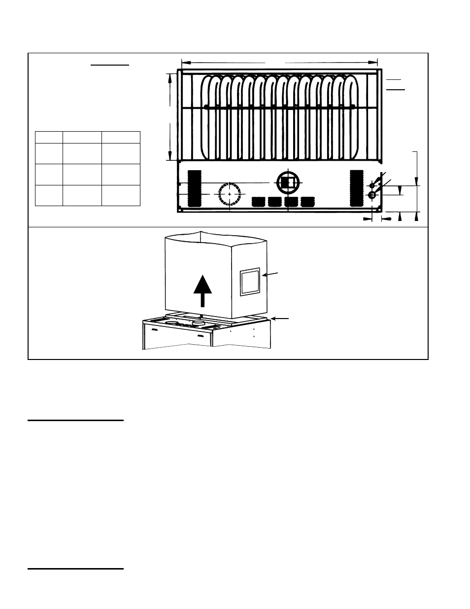
Combustion Air
Knockout
Venter
Outlet
Electrical
Gas
6-3/8
(162mm)
4-1/8
(105mm)
2-3/8 (60mm)
A
B
Discharge
Airflow
Attach to the Duct Flange
Removable Access Panel in the
Ductwork - Minimum size is 6" x 10"
(152mm x 254mm). Panel must be
sealed.
FIGURE 22B -
Connecting Discharge
Ductwork
Heater
FIGURE 22A - Top View
showing Discharge Duct
Connection Dimensions
Top
View
Size
A
B
150,
200
36"
(914mm)
21"
(533mm)
250,
300
48"
(1219mm)
21"
(533mm)
350,
400
48"
(1219mm)
34"
(864mm)
TABLE 21 - Discharge Duct
Dimensions
Requirements and
Suggestions for
Connecting and
Installing Ducts
• Type of Ductwork - The type of duct installation to be used depends in part on the
type of construction of the building.
• Ductwork Material - Rectangular duct should be constructed of not lighter than
No. 26 U.S. gauge galvanized iron or No. 24 B & S gauge aluminum.
• Ductwork Structure - All duct sections 24 inches or wider, and over 48 inches
in length, should be cross broken on top and bottom and should have standing
seams or angle-iron braces. Joints should be S and drive strip, or locked.
• Through Masonry Walls - No warm air duct should come in contact with masonry
walls. Insulate around all air duct through masonry walls with not less than 1/2" (1"
is recommended) of insulation.
• Through Unheated Space - Insulate all exposed warm air ducts passing through
unheated space with at least 1/2" (1" recommended) of insulation.
• Duct Supports - Suspend all ducts securely from buildings members. Do not sup-
port ducts from unit duct connections.
• Duct Sizing - Proper sizing of the supply air ductwork is necessary to ensure a
satisfactory heating installation. The recognized authority for such information is
the Air Conditioning Contractors Association, 2800 Shirlington Road, Suite 300,
Arlington, VA 22206 (www.acca.org). A manual covering duct sizing in detail may
be purchased directly from them.
• Removable Panels - The ducts should have removable access panels on both
upstream and downstream sides of the furnace. These openings must be acces-
sible when the furnace is in service and should be a minimum of 6" x 10" in size so
6.0 Mechanical
(cont'd)
CAUTION: An
external duct
system static
pressure not within
the limits shown
on the rating
plate, or improper
motor pulley or
belt adjustment,
may overload the
motor. See Hazard
Levels, page 2.
6.4.1 Discharge Duct Connection (cont'd)
6.4 Discharge Air (cont'd)