0 mechanical (cont'd), 2 venting and combustion air (cont'd) – Reznor CAUA Unit Installation Manual User Manual
Page 20
Form I-CAUA, P/N 164771 R8, Page 20
6.2.2 Venting and Combustion Air Requirements for Power Vent
Drawing Combustion Air from THE INSIDE SPACE and Venting
Flue Products to the Outdoors
If the environment has a positive pressure and is such that it is not detrimental to com-
bustion air, the power venting system in this section may be installed.
To provide combustion air to the heater, sufficient air must enter the equipment location
to replace that exhausted through the heater vent system. In the past, the infiltration of
outside air assumed in heat loss calculations (one air change per hour) was assumed
to be sufficient. However, current construction methods using more insulation, vapor
barriers, tighter fitting and gasketed doors and windows, weather-stripping, and/or
mechanical exhaust fans may now require the introduction of outside air through wall
openings or ductwork to the equipment room.
The requirements for combustion and ventilation air depend upon whether the unit
is located in a confined or unconfined space. An "unconfined space" is defined as a
space whose volume is not less than 50 cubic feet per 1000 BTUH of the installed
appliance.
Under all conditions, enough air must be provided to ensure there will
not be a negative pressure condition within the equipment room or space. Follow the
specific requirements below for a confined space installation.
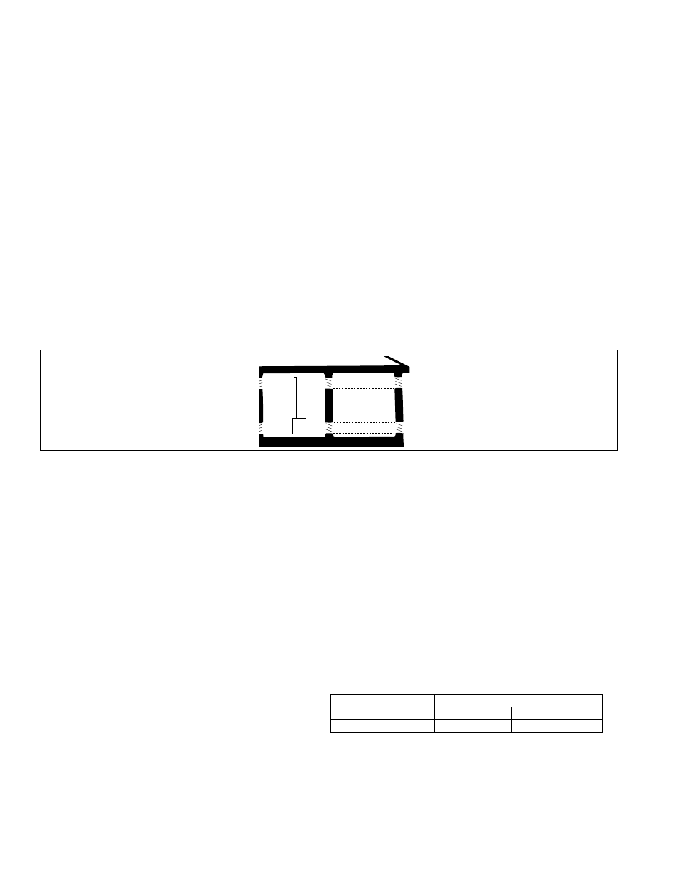
Confined Space Installation - Do not install a unit in a confined space without provid-
ing wall openings leading to and from the space. Provide openings near the floor and
ceiling for ventilation and air for combustion as shown in
FIGURE 14, depending on the
combustion air source as noted in Items 1, 2, and 3 below.
Venter Outlet
Attachment
Requirements
2) Venter (Flue) Outlet
TABLE 12 - Venter
Model Sizes
Venter Outlet Diameter
150, 200, 250
5 inches
127 mm
300, 350, 400
6 inches
152 mm
• A minimum of 12" of straight pipe is required at the venter outlet before installing
an elbow in the vent system. An elbow should never be attached directly to the
venter. An elbow attached to the straight pipe can be in any position at or above
horizontal. See
FIGURE 15.
• Do not install dampers or any other type of flue restrictor device.
All pipe is field supplied. Use either vent pipe approved for a Category III appliance or
single-wall, 26-gauge or heavier galvanized (or a material of equivalent durability and
corrosion resistance) vent pipe.
If local code requires, a double-wall terminal section may be installed with a single-wall
or Category III vent pipe run.
Or, if at least 1/2 of the equivalent vent length is vertical, vent pipe approved for a
Category I heater may be used. Single-wall pipe or double-wall (Type B) vent pipe are
suitable for use with a Category I heater.
Power Venting
Requirements
1) Type of Pipe
Outlet Size
FIGURE 14 - Confined Space:
A space whose volume is less
than 50 cubic feet per 1000
BTUH of the installed appliance
input rating
Confined
Space
(3)
(3)
(1)
(1)
(2)
(2)
Add total BTUH of all appliances in the confined space and divide by figures below for
square inch free area size of each (top and bottom) opening.
1. Air from inside the building -- openings 1 square inch free area per 1000 BTUH.
Never less than 100 square inches free area for each opening.
See (1) in FIGURE 14.
2. Air from outside through duct -- openings 1 square inch free area per 2000 BTUH.
See (2) in FIGURE 14.
3. Air direct from outside -- openings 1 square inch free area per 4000 BTUH. See
(3) in FIGURE 14.
NOTE: For further details on
supplying combustion air to
a confined space, see the
National Fuel Gas Code ANSI
Z223.1a (latest edition).
6.0 Mechanical
(cont'd)
6.2 Venting and
Combustion Air
(cont'd)