3 inlet air, 0 mechanical (cont'd), 2 venting and combustion air (cont'd) – Reznor CAUA Unit Installation Manual User Manual
Page 24: Caution: the cut edges of the metal will be sharp, 7) vent terminal (pipe and vent cap) (cont'd), Inlet air ductwork, Figure 18 - vertical vent terminals, Vertical vent terminals
Form I-CAUA, P/N 164771 R8, Page 24
6.3 Inlet Air
7) Vent Terminal (Pipe and Vent Cap) (cont'd)
6.0 Mechanical
(cont'd)
6.2 Venting and
Combustion Air
(cont'd)
6.2.2 Venting and Combustion Air Requirements for Power Vent
Drawing Combustion Air from THE INSIDE SPACE and Venting
Flue Products to the Outdoors (cont'd)
Inlet air ductwork is
required unless equipped with inlet base Option AVA2. Filters
are recommended when a cooling coil is part of the installation. Inlet air may be 100%
return air, a mixture of return and outside air (air entering the blower must be 35°F or
higher unless equipped with makeup air Option AD4), or 100% outside air if equipped
with makeup air Option AD4.
TABLE 15 - Inlet Air
Opening Dimensions
Inlet Air Opening Dimensions
Sizes
150, 200
250, 300
350, 400
inches
mm
inches
mm
inches
mm
Without Optional Filter or Mixing Cabinet (actual cutout opening on heater)
Right Side
31 x 16
787 x 406
31 x 16
787 x 406
44 x 16
1118 x 406
Left Side
31 x 16
787 x 406
31 x 16
787 x 406
44 x 16
1118 x 406
Rear
33 x 16
838 x 406
45 x 16
1143 x 406
45 x 16
1143 x 406
Bottom
25-1/2 x 32 648 x 813 37-1/2 x 32
953 x 813 37-1/2 x 46 953 x 1168
With Optional Side or Rear Filter Cabinet (duct opening in top or rear of cabinet)
Attached to Heater Side
32 x 16
813 x 406
32 x 16
313 x 406 45-1/8 x 16 1146 x 406
Attached to Heater Rear
32 x 16
813 x 406 45-1/8 x 16 1146 x 406 45-1/8 x 16 1146 x 406
With Optional Bottom Filter Cabinet (duct opening in bottom of cabinet)
Under Heater
25-1/2 x 32 618 x 813 37-1/2 x 32
953 x 813 37-1/2 x 46 953 x 1168
With Optional Mixing Box (duct opening in top, bottom, or rear of cabinet)
Attached to Heater Rear 22 x 19-1/2 578 x 495
36-1/2 x
19-1/2
927 x 495
36-1/2 x
19-1/2
927 x 495
The location of the inlet air duct connection depends on the installation. Corner indica-
tors for the opening are provided on the right side, the left side, the rear, and the bottom
of the heater. (See Dimensions in
FIGURE 1, page 5.) Determine where the inlet air
opening(s) should be and cut out using tin snips or aviation shears.
CAUTION: The cut edges of the metal will be sharp.
Inlet Air Ductwork
If installing an optional filter or filter/mixing cabinet shipped with the heater, attach the
cabinet at the "cutout" opening.
Attach the ductwork to the heater or to the inlet cabinet.
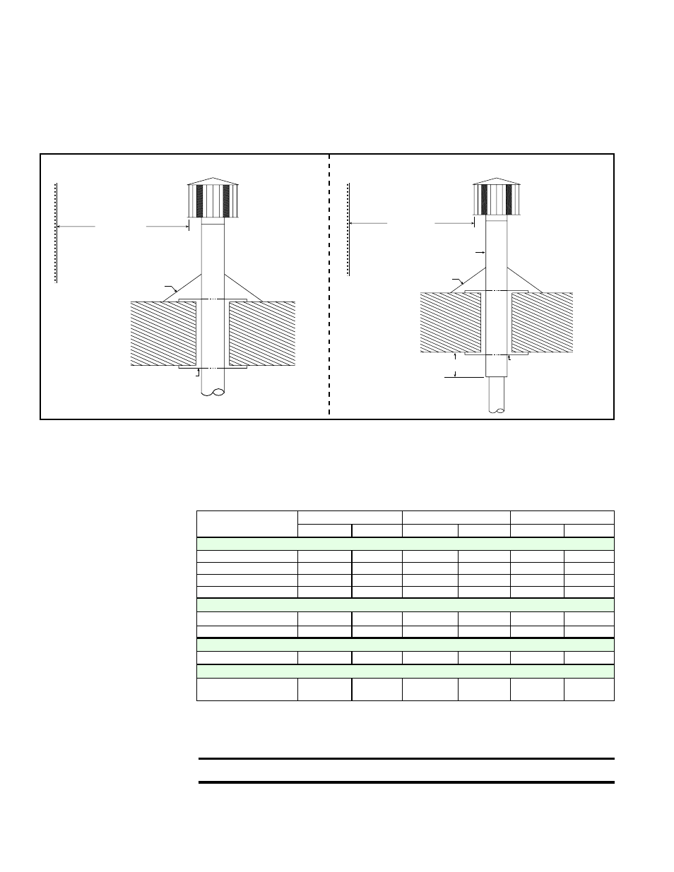
FIGURE 18 - Vertical Vent Terminals
Roof -
pitched
from
0 to 45°
A clearance thimble is required
when flue pipe extends through
combustible materials.
Follow the requirements of the
thimble or vent pipe manufacturer.
Vertical flue extension
must be 6 (152mm)
higher than anticipated
snow depth but no less
than 2 ft (610mm)
above the roof.
Roof Flashing
Parapet or
Adjoining Building
6 ft (1.8M)
minimum
Reznor (Option
CC1) vent cap
Roof -
pitched
from
0 to 45°
A clearance thimble
is required when flue
pipe extends through
combustible materials.
Follow the requirements
of the double-wall pipe
manufacturer.
*Follow the illustrated instructions
in FIGURES 16B and 16C to join the
double-wall vent terminal section to
the vent run and to attach the vent cap.
Vertical flue extension
must be 6 (152mm)
higher than anticipated
snow depth but no less
than 2 ft (610mm)
above the roof.
Roof Flashing
6 (152mm) minimum
Parapet or
Adjoining Building
6 ft (1.8M)
minimum
Double Wall Pipe*
Reznor (Option CC1)
vent cap
Single-Wall Vent Run and Single-Wall Terminal
Single-Wall Vent Run and Double-Wall Terminal
NOTE: Drawings are not proportional; read all measurements.
Vertical Vent Terminals