0 mechanical (cont'd), 2 venting and combustion air (cont'd), 8) concentric adapter box – Reznor CAUA Unit Installation Manual User Manual
Page 12: Concentric adapter box dimensions, View of heater connection side
Form I-CAUA, P/N 164771 R8, Page 12
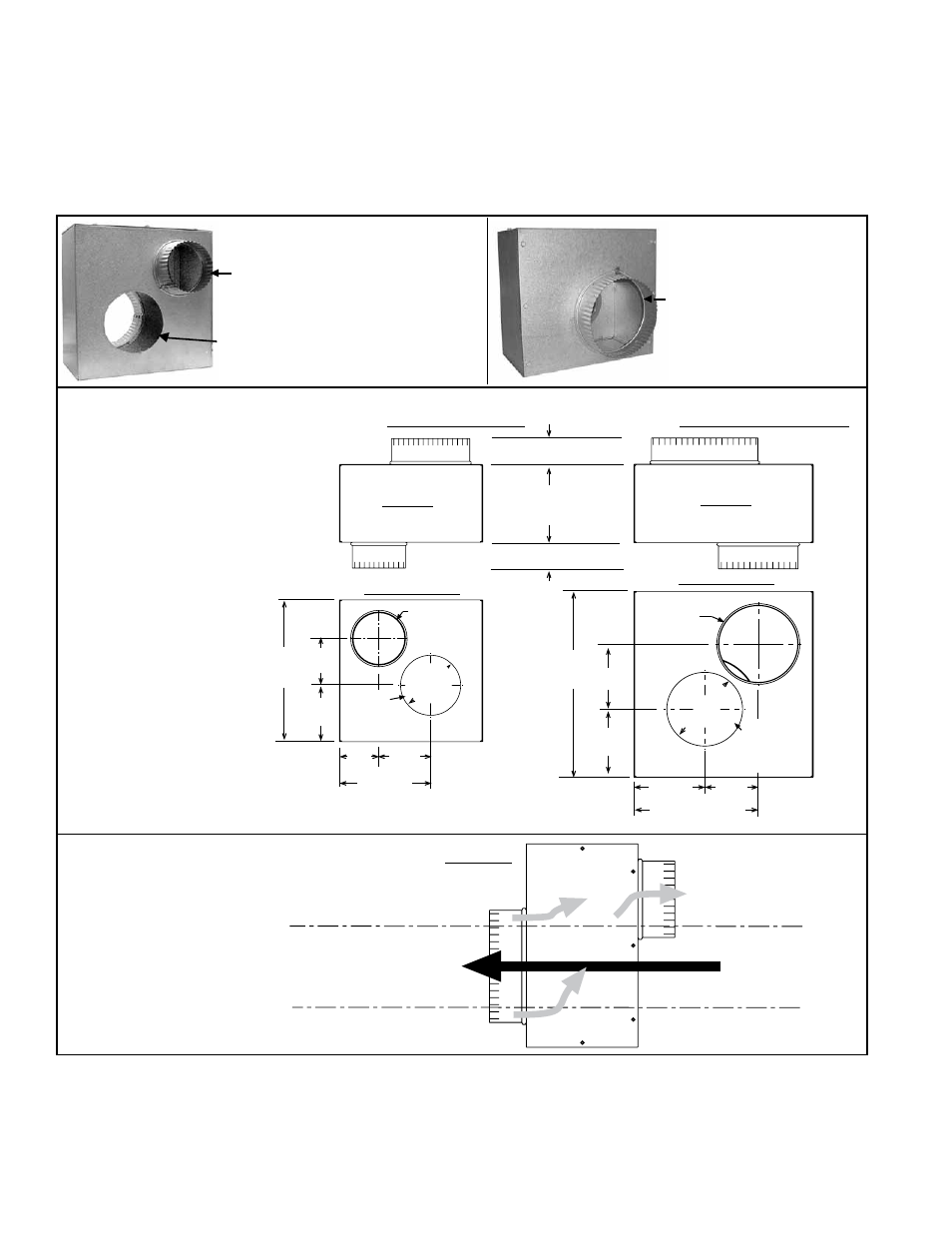
FIGURE 5 - Concentric Adapter Box Description, Dimensions, and Airflow
End View
showing
Airflow
Gray Arrows
show Flow of
Combustion Air
Vent (exhaust gas) flows through
field-supplied double-wall pipe
that extends straight through
the concentric adapter box.
View of Vent Terminal
Connection Side
Concentric
Adapter Box
Airflow
Collar for connecting
indoor portion of the
combustion air pipe
Opening for double-wall vent
pipe to pass through the box.
Collar for attaching
outside concentric
portion of the
combustion air pipe
P/N 205884, Concentric Adapter Box, in Kits 205882
and 205895 used on CAUA Sizes 150 and 200
P/N 205885, Concentric Adapter Box, in Kits 205883
and 205896 used on CAUA Sizes 250, 300, 350, 400
Top View
Top View
Heater Side View
Heater Side View
4 dia.
Combustion
Air Collar
6 Combustion
Air Collar
Opening for
vent pipe to
pass through
the box
Opening
for vent
pipe to pass
through the box
2 (51mm)
2 (51mm)
6-1/32 (153mm)
6 dia Collar for
Combustion Air
8 dia Collar for
Combustion Air
11
(279mm)
3-5/8
(92mm)
4-3/8
(111mm)
11-3/32
282mm
4
(102mm)
3-1/16 (78mm)
14-1/4
(362mm)
5
(127mm)
5-7/32
(133mm)
5 (127mm)
diameter
5-9/32
(134mm)
4
(102mm)
13-3/8 (340mm)
4
(102m
m)
diam
eter
Concentric
Adapter Box
Dimensions
All separated combustion installations
require a concentric adapter box as illustrated
in
FIGURE 5.
The concentric adapter box is included in the vent/combustion air kit. Installation
instructions depend on whether the vent system is horizontal (Option CC6) or vertical
(Option CC2).
8) Concentric Adapter Box
View of Heater Connection Side
When vent pipe diameters differ, join the pipes with a taper-type reducer. Refer to
FIG-
URE 6A, 6B, or 6C for pipe connection requirements at the concentric adapter box.
Do
NOT make actual connections until after reading the instructions and length require-
ments for installing the vent/combustion air kit.
The connection requirements are
the same for both vertical and horizontal systems, but pipe length requirements
vary.
6.0 Mechanical
(cont'd)
6.2 Venting and
Combustion Air
(cont'd)