0 ignition system – Reznor CAUA Unit Installation Manual User Manual
Page 39
Form I-CAUA, P/N 164771 R8, Page 39
If there is a remote console (Option RC_) and there is a dirty filter indicator light on
the console, there is a dirty filter switch either in the optional mixing box or in the main
electrical compartment. After the unit is started, before continuous operation, the dirty
filter switch must be set.
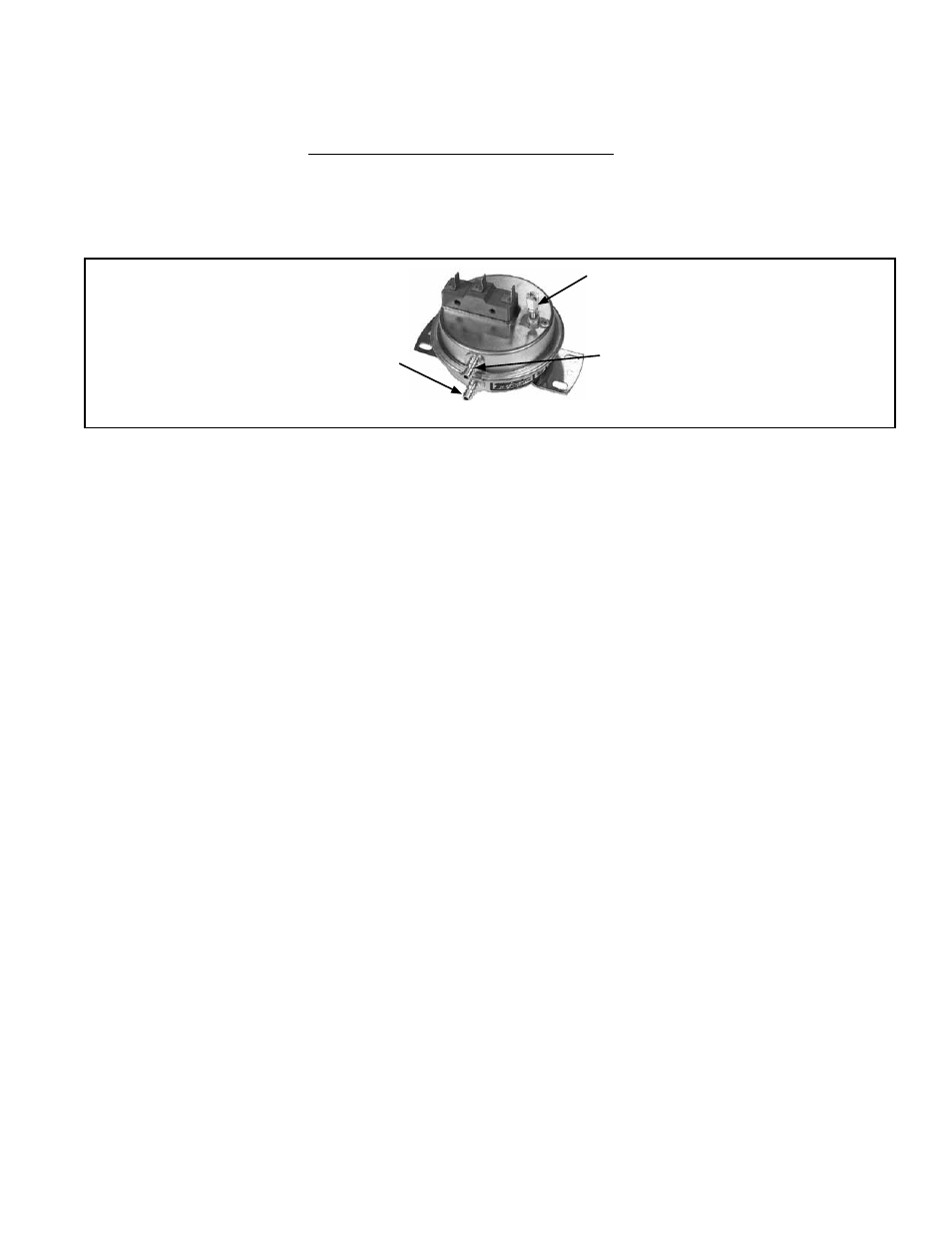
FIGURE 31 - Dirty Filter Switch,
P/N 105507 (must be set prior to
continuous operation)
Set screw (on front of switch) must
be manually adjusted after the
system is in operation.
Negative pressure connection is
toward the “front or top” of the
switch (senses blower side of filters)
Positive pressure connection is
toward the “back or bottom” of the
switch (senses air inlet side of filters)
7.4.2 Dirty Filter
Switch
8.0 Ignition
System
A Model CAUA heater is equipped with a direct spark integrated control system. The
system monitors the safety devices and controls the operation of the blower and venter
motors and the gas valve.
Ignition System Operating Sequence
On a call for heat from the thermostat, the system energizes the venter motor and
goes through a 10-second prepurge. The system verifies that the pressure switch has
changed states closing the normally open contactor and that the high limit is in the
closed state.
The gas valve is then energized, and the ignition system provides the high voltage
spark to the electrode to ignite the main burner gas. Burner flame is electronically
sensed by the control (minimum 1.0 microamps) upon carryover of all burners. (A sep-
arate solid metal probe is used as the flame sensing function. A low voltage electrical
signal is imposed on the metal probe which is electrically isolated from ground. When
the flame impinges on the flame sensing probe, the flame acts as a conduction path
to ground. The flame rectifies and completes the DC circuit, and the ignition system
acknowledges the flame.)
The blower motor is energized by the system after 30 seconds of flame sensing.
After the thermostat has been satisfied, the system de-energizes the gas valve, the
venter motor goes through a 45-second post-purge, and the blower motor remains
energized for an additional 135 seconds.
NOTE: This is a three trial system. The unit will lockout for one hour before initiating
another trial for ignition. If the unit fails after one recycle interval, the unit will go into
hard lockout and must be reset by interrupting power or resetting the thermostat. To
initiate another trial for ignition before the one hour interval, either reset the thermostat
or interrupt power to the unit for 30 seconds.
Instructions for Setting Dirty Filter Switch (FIGURE 31) - With clean filters in place;
all doors closed (except electrical compartment); and the blower opening, increase the
pressure setting by adjusting the setscrew on the switch clockwise until the filter light
is energized or the screw is bottomed out. At that point, adjust the setscrew three full
turns counter clockwise or until the screw is top ended. At that setpoint, the filter light
will be activated at approximately 50% filter blockage.