6 cased cooling coil, model acua, acub, Or acuc or option c, Caution – Reznor CAUA Unit Installation Manual User Manual
Page 31
Form I-CAUA, P/N 164771 R8, Page 31
6.6 Cased Cooling
Coil, Model
ACUA, ACUB,
or ACUC or
Option C
This cased cooling coil is designed for use with the Model CAUA upflow heater. It is
shipped separately for field installation over the discharge opening of the heater. Before
installing, verify that the coil cabinet is the same size as the heater cabinet.
Follow the installation instructions shipped with the cooling coil (Installation Form
I-CAUA-CC), the wiring diagram, and the instructions provided by the condenser unit
manufacturer.
The cased cooling coil is for use with R-410A refrigerant and requires field installation
of the shipped-loose thermostatic expansion valves and reducers (if required). (
NOTE:
A coil installed prior to 12/09 most likely is charged with R22 refrigerant; check the rat-
ing plate. Due to higher pressures, do not use tools designed for R22 refrigerant with
R410A refrigerant.)
Depending on size and option selection, coils may have a single circuit (Sizes 060 and
072 only), have two 50/50 circuits, or have two circuits that are 1/3-2/3 designed to
match the Reznor
®
Model MASA condensing unit.
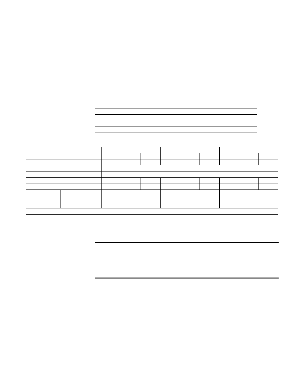
Heater Model CAUA
150
200
250
300
350
400
ACUA or Opt C
ACUB or Opt C
ACUC or Opt C
060
090
120
072
120
150
090
150
180
TABLE 23 - Heater/Coil
Cross-Reference by
Cabinet Size
Model
ACUA
ACUB
ACUC
Size
60
72
90
90
120
150
120
150
180
Nominal Cooling Capacity (MBH)
60
72
90
90
120
150
120
150
180
Refrigerant Type
R-410A. (
NOTE: Prior to 12/09, refrigerant type may be R22.)
Thermostatic Expansion Valves
Shipped loose for field installation; see Form I-CAUA-CC.
Approximate Weight (lbs)
83
86
105
110
122
140
176
180
188
Face Area (sq ft)
7.79
7.79
9.38
14.04
11.67
13.7
17.13
15.38
17.13
Airflow (cfm)
Low
1800
3000
4000
Nominal
2400
4000
5000
High
3000*
5000*
6000*
* Airflow in excess of maximum values shown may result in blow-off of condensation.
TABLE 24 - Cased Cooling Coil Technical Data
Thermostatic
Expansion Valves
Verify the thermostatic expansion valves and reducers shipped with the coil with the
appropriate list in Form I-CAUA-CC. Follow the instructions provided to install the ther-
mostatic expansion valve(s) and reducer(s), if required.
CAUTION:
The thermostatic expansion valve must be for the
right refrigerant and must be sized to match the circuit. Failure
to properly select and install the thermostatic expansion valve
will prevent the system from operating properly and will void the
manufacturer’s warranty.
After the refrigerant lines are installed and before charging, extend the thermostatic
expansion valve bulb from the valve to the suction line. If there are two circuits, be sure
to match the liquid line with the corresponding suction line. Comply with the valve man-
ufacturer’s instructions on bulb placement. General recommendations are listed below.
•
Place bulb on suction line as close to the evaporator coil outlet as possible.
•
Place the bulb on a straight horizontal section of suction line (if bulb must be
vertical, line must be descending).
•
Never place bulb in a trap or downstream of a trap.
•
Position bulb as shown in
FIGURE 25A.
•
Bulb must have 100% contact with tubing.
•
Secure the bulb tightly.
•
Cover bulb with waterproof insulation.