4 discharge air – Reznor CAUA Unit Installation Manual User Manual
Page 27
Form I-CAUA, P/N 164771 R8, Page 27
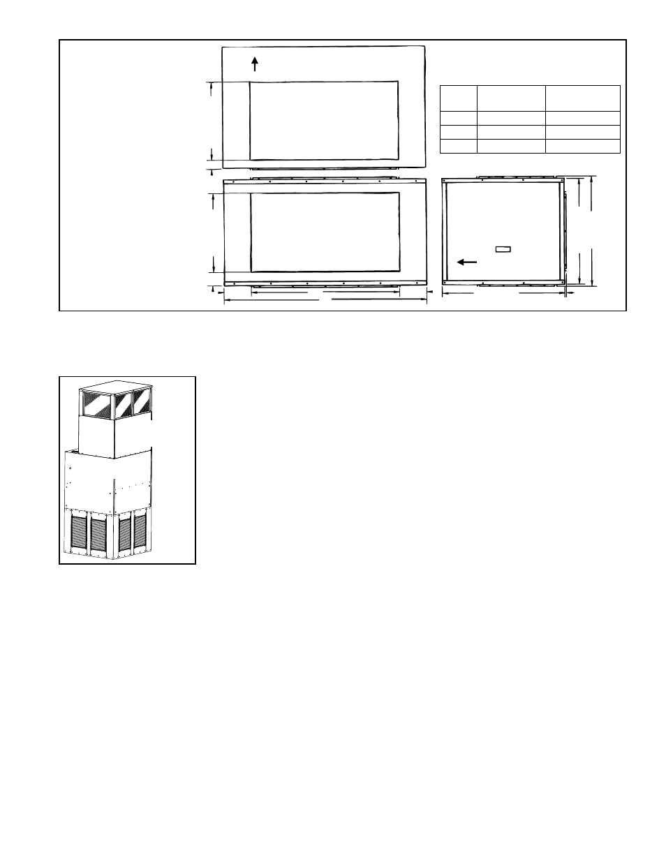
FIGURE 20 -
Dimensions of
Optional Mixing
Box - inches (mm)
Top View
Rear View
Inlet Opening with
Duct Flange
Inlet Opening with
Duct Flange
(If bottom inlet, opening is
symmetrical with top view.)
19-1/2 (495)
2 (51)
19-1/2 (495)
3-3/8 (86)
A
B
C
C
Airflow
Side View
(Removable Filter
Access Door)
Airflow
39-1/8 (765)
26-1/8 (664)
27 (686
)
3/8 (10)
Typ.
Note: Damper
frame fits in the inlet
opening.
TABLE 20 - Mixing Box
Dimensions - inches (mm)
CAUA
Size
150, 200
250, 300,
350, 400
A
38 (965)
50 (1270)
B
22-3/4 (578) 36-1/2 (927)
C
7-5/8 (194)
6-3/4 (171)
A discharge plenum adds 49-15/16" (1268mm) to the height of the heater. (If installing
Option CD62, this height includes the cooling coil.)
The optional mounting base is designed to support a Model CAUA 350 or The optional
mounting base is designed to support a Model CAUA 350 or 400 heater while providing
an inlet for return air. The mounting base is designed to be used with an optional dis-
charge plenum (Paragraph 6.4.1) creating a "packaged stand-alone" heating or heat-
ing/cooling upflow system which can be used in an air turnover application.
However, if the installation requires it, the mounting base may also be used with dis-
charge ductwork.
The mounting base has guarded openings on all four sides and is available with
optional 1" flat disposable, 1" permanent aluminum, or 1" pleated disposable filters.
The base is designed for a fairly open area and must have at least three of the four
sides open.
The base adds 36-1/2" (927mm) to the overall height.
6.3.3 Inlet Base, Option AVA (Sizes 350 and 400 only)
Inlet
Base
CAUA
Discharge
Plenum
FIGURE 21 - Inlet Base
and Discharge Plenum
Options
The discharge duct connects to the top of the heater or to the outlet of the optional
cooling coil cabinet. See
FIGURES 22A and 22B. Connect the ductwork plenum to the
duct flange as illustrated in
FIGURE 22B.
1) The duct connection on the top of the heater has a 90° flange.
2) The duct may either have no flange or a 90° flange.
3) Position ductwork around the outside of the heater flange.
4) If the ductwork has a flange, drill holes vertically through duct flange into the top
of the heater and secure with sheetmetal screws. If the ductwork does not have
a flange, drill holes horizontally through the ductwork and the heater flange;
secure with sheetmetal screws.
6.4.1 Discharge Duct Connection
6.4 Discharge Air
Installation NOTE: If being
installed as a makeup
air unit with two-stage
control (Option AG3),
see Paragraph 6.4.3 for
instructions on installing the
duct sensor.