Warning, Table 4 - sizing a gas supply line, Gas piping requirements and connection – Reznor CAUA Unit Installation Manual User Manual
Page 7: Gas valve
Form I-CAUA, P/N 164771 R8, Page 7
TABLE 4 -
Sizing a Gas
Supply Line
Capacity of Piping - Cubic Feet per Hour based on 0.3" w.c. Pressure Drop
Specific Gravity for Natural Gas -- 0.6 (Natural Gas -- 1000 BTU/Cubic Ft)
Specific Gravity for Propane Gas -- 1.6 (Propane Gas -- 2550 BTU/Cubic Ft)
Length
Diameter of Pipe
of
1/2"
3/4"
1"
1-1/4"
1-1/2"
2"
Pipe
Natural
Propane
Natural
Propane
Natural
Propane
Natural Propane Natural Propane Natural Propane
20'
92
56
190
116
350
214
730
445
1100
671
2100
1281
30'
73
45
152
93
285
174
590
360
890
543
1650
1007
40'
63
38
130
79
245
149
500
305
760
464
1450
885
50'
56
34
115
70
215
131
440
268
670
409
1270
775
60'
50
31
105
64
195
119
400
244
610
372
1105
674
70'
46
28
96
59
180
110
370
226
560
342
1050
641
80'
43
26
90
55
170
104
350
214
530
323
990
604
90'
40
24
84
51
160
98
320
195
490
299
930
567
100'
38
23
79
48
150
92
305
186
460
281
870
531
125'
34
21
72
44
130
79
275
168
410
250
780
476
150'
31
19
64
39
120
73
250
153
380
232
710
433
175'
28
17
59
36
110
67
225
137
350
214
650
397
200'
26
16
55
34
100
61
210
128
320
195
610
372
Note: When sizing supply lines, consider possibilities of future expansion and increased requirements.
Refer to National Fuel Gas Code for additional information on line sizing.
Gas Piping
Requirements and
Connection
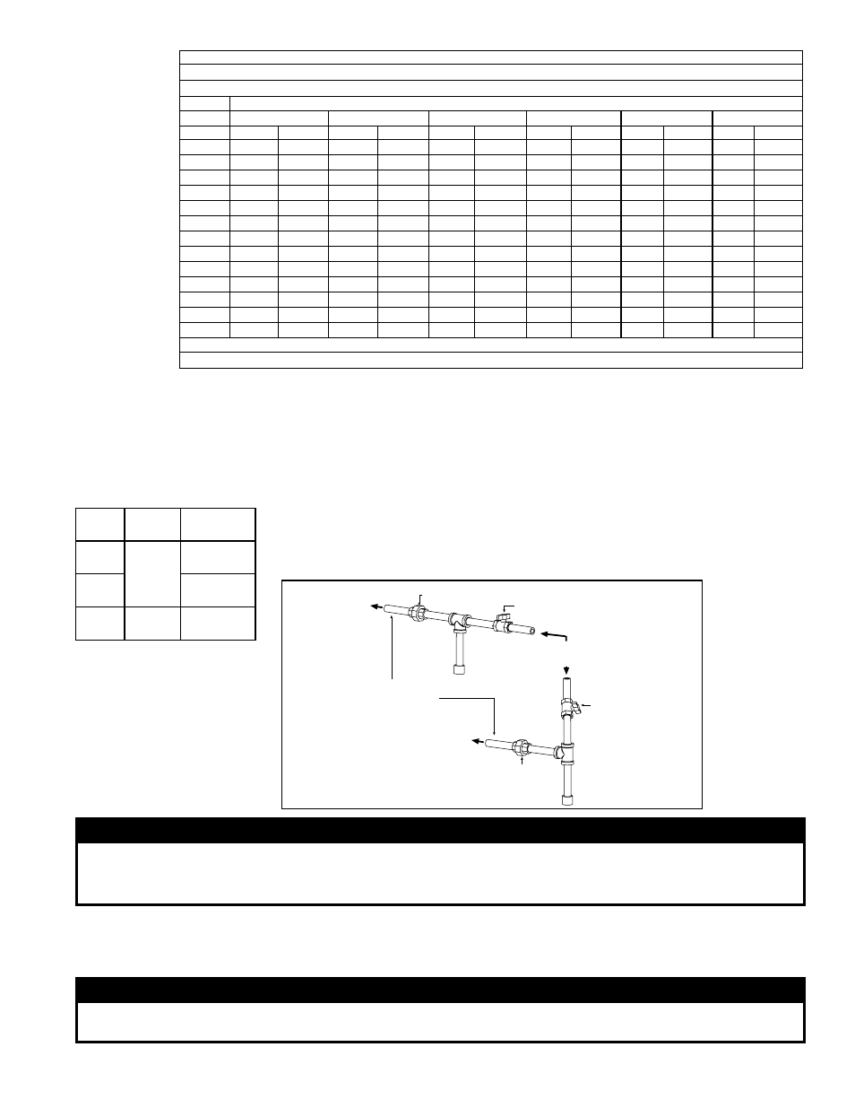
Pipe joint compounds (pipe dope) shall be resistant to the action of liquefied
petroleum gas or any other chemical constituents of the gas being supplied.
Install a ground joint union and manual shutoff valve upstream of the unit control
system as shown in
FIGURE 2. The 1/8" plugged tapping in the shutoff valve pro-
vides connection for a supply line pressure test gauge. The National Fuel Gas Code
requires the installation of a trap with a minimum 3" (76mm) drip leg. Local codes may
require a minimum drip leg longer than 3", typically 6" (152mm). Bleed gas lines of
trapped air.
Gas connection is either 1/2" or 3/4" depending on size and type of gas (See
TABLE
5).
Leak-test all connections by brushing on a leak-detecting solution.
TABLE 5 - Gas
Connection (not supply
line size)
FIGURE 2 - Supply
Piping Connection
WARNING
All components of a gas supply system must be leak tested prior to placing equipment in service.
NEVER TEST FOR LEAKS WITH AN OPEN FLAME. Failure to comply could result in personal injury,
property damage or death.
CAUA
Sizes
Fuel
Gas
Connection
150-
200
Natural
Gas
1/2"
250-
400
3/4"
150-
400 Propane
1/2"
From Gas Supply
(horizontal or vertical)
Manual shutoff
Pipe nipple extending
outside the cabinet.
Drip
Leg
To Gas Valve
(inside the
cabinet)
To Gas Valve
(inside the
cabinet)
Ground
Joint
Union
Drip
Leg
Ground Joint Union
Manual shutoff
Gas Valve
The main operating gas valve is powered by the 24-volt control circuit through the
thermostat and safety controls. The main control valve is of the diaphragm type pro-
viding regulated gas flow preset at the factory.
WARNING:
The operating valve is the prime safety shutoff. All gas supply lines must be free of dirt or scale
before connecting the unit to ensure positive closure. See Hazard Levels, page 2.