Reznor CAUA Unit Installation Manual User Manual
Page 41
Form I-CAUA, P/N 164771 R8, Page 41
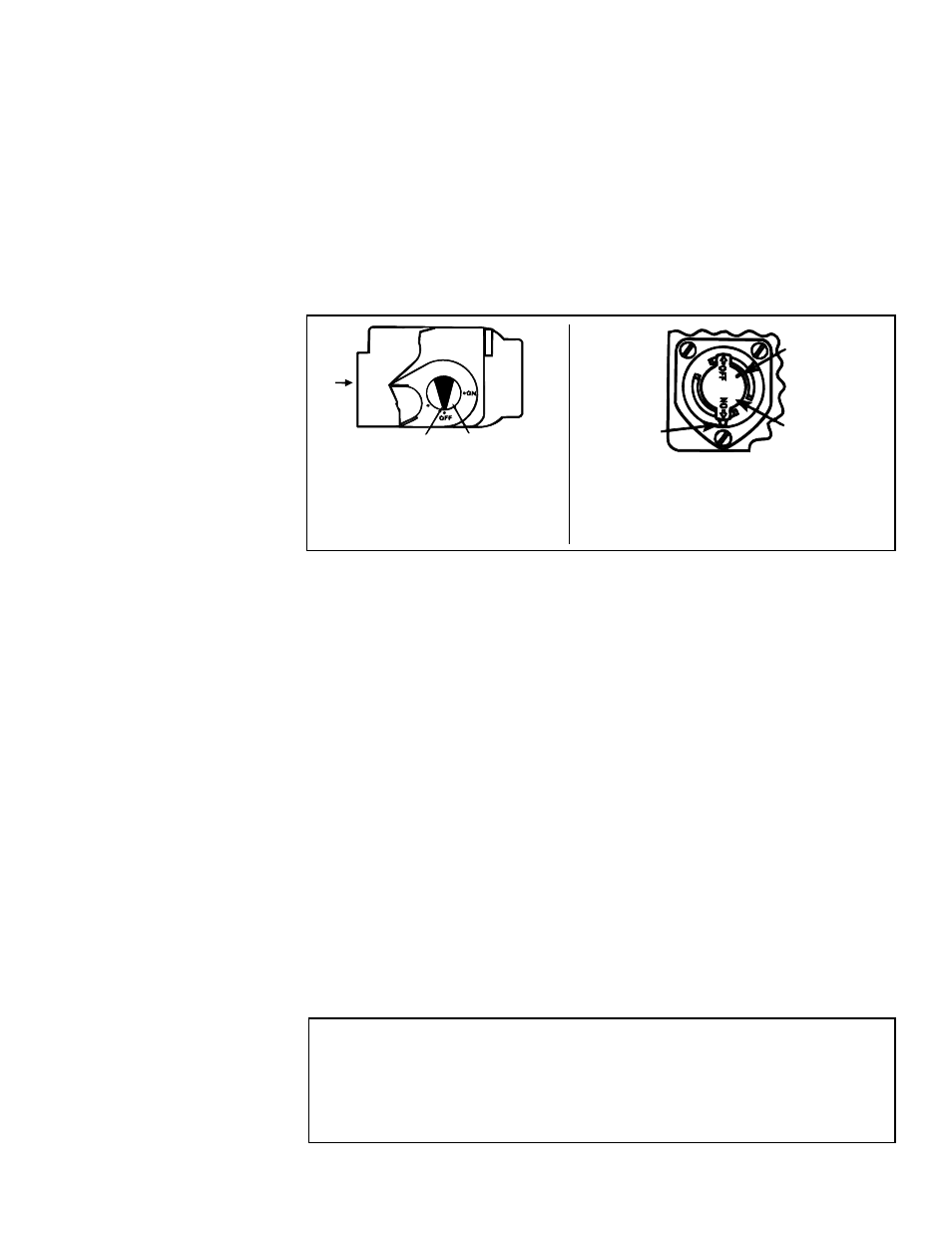
4. Models CAUA 150 and 200 - Locate the gas control (ON/OFF) knob on the gas
valve. Turn the gas control knob clockwise to "OFF".
Models CAUA 250, 300, 350, and 400 - Locate the gas control (ON/OFF) knob on
the gas valve. Turn knob clockwise to align the line on the knob with the position
indicator. Depress knob and continue rotation to the "OFF" position.
5. Wait five (5) minutes to clear out any gas. Then smell for gas, including near the
floor.
If you smell gas, STOP! and follow the steps in the WARNINGS printed on
the previous page or on the Operating Label on the heater. If you do not smell gas,
proceed to the next step.
6. Models CAUA 150 and 200 - Turn the gas control knob counterclockwise to "ON".
Models CAUA 250, 300, 350, and 400 - Turn knob counterclockwise to align the
line on the knob with the position indicator. Allow knob to "pop up", and continue
rotation to the "ON" position.
Operating Instructions
and Operating
Sequence
Gas
Flow
Position
Indicator
Gas Control
Knob
Top View of Single-Stage Gas
Valve used on CAUA 150 and
200
FIGURE 32 - Gas Valve
Controls
Line
Gas
Control
Knob
Position
Indicator
Control Knob on Top of Single-
Stage Gas Valve used on CAUA
250, 300, 350, and 400
NOTE: Single-stage valves
are illustrated; optional two-
stage valves are similar.
7. Close the access door.
8. Turn on the electric power to the heater.
9. Set the thermostat to the desired setting.
NOTE: If the appliance does not operate, follow the instructions "To Turn Off Gas to the
Appliance" printed below (and on the Operating Label on the heater). Call your service
technician.
10. Thermostat calls for heat, energizing the venter motor.
11. Venter pressure switch closes, allowing the unit to fire.
12. Burner flame is sensed and in 30 seconds, the blower motor is energized.
13. If the flame is extinguished during the main burner operation, the integrated con-
trol system closes the main valve and must be reset by interrupting power to the
control circuit. (See lighting instructions on heater.).
Vent System Testing Procedure - Power Vent Units (does not apply to sepa-
rated-combustion installation - Option CC2 or CC6)
1. Seal any unused openings in the venting system.
2. Inspect the venting system for proper size and horizontal pitch, as required in
the National Fuel Gas Code, ANSI Z223.1 or CAN/CSA B149.1 and B149.2,
Installation Code for Gas Burning Appliances and Equipment, and this manual.
Determine that there is no blockage or restriction, leakage, corrosion and other
deficiencies which could cause an unsafe condition.
3. In so far as practical, close all building doors and windows and all doors
between the space where the heater is and other spaces of the building.
Turn on clothes dryers and exhaust fans, such as range hoods and bathroom
1) Set thermostat to lowest setting
2) If service is to be performed, turn off electric power to the appliance.
3) Open the access door.
4) Turn the gas control knob to "OFF" (follow instructions in No. 4 above). Do not
force control knob.
5) Close the access door.
TO TURN OFF GAS TO
THE APPLIANCE