Reznor CAUA Unit Installation Manual User Manual
Page 21
Form I-CAUA, P/N 164771 R8, Page 21
3) Vent Pipe Diameter
and Length
NOTE: If the system contains all vertical pipe or a combination of horizontal and vertical
vent pipe, the Maximum Permissible Vent Length may be increased one foot (305mm)
for each foot (305mm) of vertical rise up to a maximum increase of ten feet (3M).
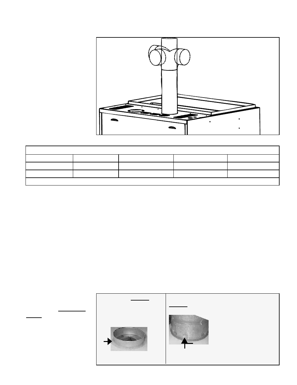
FIGURE 15 - Alternate
Vent Directions
Vent in any
position above
horizontal.
A minimum of 12" (305mm) of
straight pipe is required before an
elbow.
NOTES:
•
A minimum of 12"
(305mm) of straight pipe
is required before an
elbow.
•
If installing a double-wall
vent run (allowed if 1/2
of vent length is verti-
cal), see
FIGURE 16A for
attaching the vent pipe to
the heater.
4) Joints and Sealing
TABLE 13 - Vent Pipe Diameter and Length
Maximum Vent Length - Minimum length is 5 ft (1.5M).
CAUA Sizes
Pipe Diameter
Maximum Length
90°
Elbow Equals *
45° Elbow Equals *
150, 200, 250
5" (127mm)
50 ft (15.2M)
5 ft (1.5M)
2.5 ft (.8M)
300, 350, 400
6" (152mm)
50 ft (15.2M)
5 ft (1.5M)
2.5 ft (.8M)
*Reduce by this amount for each elbow.
Provide field-supplied vent pipe as specified in Requirement No. 1 above.
• If using
single wall, 26-gauge or heavier galvanized pipe, secure slip-fit
connections using sheetmetal screws or rivets. Seal pipe joints either with tape
suitable for 550°F (such as Option FA1, P/N 98266) or high-temperature silicone
sealant.
• If using
Category III vent pipe, follow pipe manufacturer's instructions for joining
pipe sections. When attaching Category III pipe to the venter outlet or the vent
cap, make secure, sealed joints following a procedure that best suits the style of
Category III pipe being used.
• If installing a
double-wall (Type B) terminal pipe, follow the instructions in
FIGURE 16B to join the double-wall pipe to a single-wall or Category III vent pipe
run. To attach the vent cap, follow instructions in
FIGURE 16C.
• If using
double-wall (Type B) vent pipe in the vent pipe run (at least 1/2 of the
equivalent vent length must be vertical), follow the pipe manufacturer's instructions
for joining pipe sections. For attaching double-wall pipe to the heater, see
FIGURE
16A. To attach the vent cap, see FIGURE 16C.
Figure 16A - STEP 1
Place a continual 1/4” bead
of silicone sealant around the
circumference of the venter
outlet collar.
Figure 16A -
STEP 2
Slide the double-wall pipe over
the collar so that the collar is
inside the inner pipe. Push the
double-wall pipe tight to the
heater cabinet. To secure the
connection, spaced equal dis-
tance around the pipe, drill and
insert three 3/4” long sheet-
metal screws through the pipe
and into the collar. Do not over
tighten the screws.
FIGURE 16A - Attaching
Double-Wall (Type-B)
Vent Pipe to the Venter
Outlet
A double-wall pipe run
is allowed only if at least
1/2 of the vent length is
vertical.
Do STEP 2 immediately
after STEP 1.