Reznor CAUA Unit Installation Manual User Manual
Page 19
Form I-CAUA, P/N 164771 R8, Page 19
SECOND, Install the Exhaust (Vent) Terminal.
Follow the instructions in FIGURE 4A, page 11.
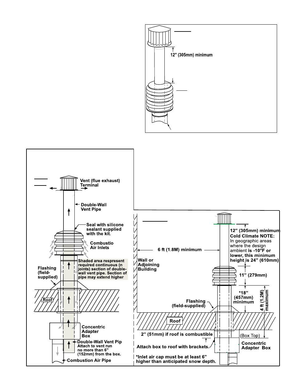
FIRST, Install Combustion Air Inlet.
1) Slide the combustion air inlet over the vent pipe.
2) Fasten bottom of inlet to the combustion air pipe
with sheetmetal screws. Be sure not to penetrate
the vent pipe.
3) At the top, completely seal the space between the
vent pipe and the air inlet with silicone.
Double-wall V
ent Pipe
Cold Climate NOTE: In geographic areas
where the design ambient is -10°F or lower,
this minimum height is 24” (610 mm)
Single-wall Combustion Air Pipe
FIGURE 12 -
Install Combustion Air Inlet and Vent Terminal
the end is no more than 6" (152mm) below the
box. The upper end should extend at least 3"
(76mm) above the combustion air pipe.
NOTE:
The double-wall vent pipe does not attach to the
box.
The installer must provide support.
Follow the instructions in
FIGURE 4B, page 11,
for connecting the double-wall pipe to the single-
wall pipe or Category III vent pipe run. For CAUA
Sizes 150, 200, 300, 350, and 400, a taper-type
reducer is required.
Seal the circumference of the pipe and the open-
ing of the box with silicone sealant. Seal the area
around the pipe completely.
7) On the outside, slide the combustion air
inlet over the vent pipe and fasten the collar to
the combustion air pipe with sheetmetal screws.
See
FIGURE 12. Seal the opening at the top
between the vent pipe and the combustion
air inlet with silicone sealant to prevent water
leakage.
8) Attach the exhaust (vent) cap. Follow the illustrated
instructions in
FIGURE 4A, page 11.
FIGURE 13 - Installation of Unit with
Vertical Vent Terminal/Combustion Air
Inlet (Option CC2)
Rear
View
Side View
9) Attach the indoor combustion air pipe. Use sheetmetal
screws to attach the single-wall combustion air pipe run to the
collar on the concentric adapter box. On Sizes 150 and 200,
install a taper type enlarger as illustrated in
FIGURE 6A, page
13.
Seal joint with tape or sealant.
Installation of the vertical vent and combustion air system on
your separated-combustion unit is complete.
Verify compliance
with all venting installation requirements, pages 9-13, and
FIGURE 13.