Reznor CAUA Unit Installation Manual User Manual
Page 17
Form I-CAUA, P/N 164771 R8, Page 17
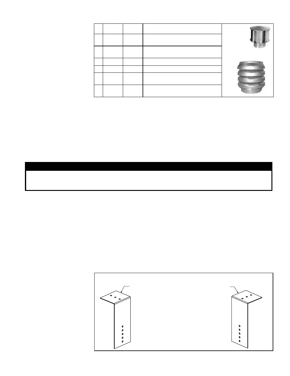
TABLE 11 - Parts in
Option CC2, Vertical
Vent Terminal/
Combustion Air
Package
Components Required - Factory and Field
6.2.1.2 VERTICAL
Vent Instructions
Field-supplied
installation
requirements:
• Vent pipes - see requirements, page 9.
• Combustion air pipes - see requirements, page 9.
• Taper-type pipe diameter reducers and/or increasers as required.
• Thimble (a thimble is not required if wall is of non-combustible construction).
• Flashing.
• Sheetmetal screws, tape, and sealant as required.
Installation Instructions
for Vertical Vent/
Combustion Air Kit
Option CC2
1) Determine the location of the vent terminal.
Select a location away from fresh air intakes, allowing space for the concentric
adapter box inside. Vent terminal must be located from adjacent buildings as shown
in
FIGURE 13, page 19.
Exhaust
(Vent)
Terminal
Combustion
Air Inlet
Qty
150,
200
250, 300,
350, 400
Description
1 205895 205896 Complete Vertical Vent Kit (Same
as Option CC2)
1 205884 205885 Concentric Adapter Box Assembly
(See
FIGURE 5, page 12)
1 110051 110052 Exhaust (Vent) Terminal
1 155635 53330 Combustion Air
2 207232 207232 Brackets for attaching Concentric
Adapter Box (See
FIGURE 9, pg 19)
1
53335
53335 Tube of High Temperature Silicone
Sealant
4) Prepare the Concentric
Adapter Box
a. Attach the brackets to
the box. Follow the instruc-
tions in
FIGURE 9.
FIGURE 9 - Brackets
for Attaching the
Concentric Adapter Box
to the Roof
1) Attach the Brackets to the Box - The 6
(152mm) portion of each bracket is designed
with five 7/32 diameter holes so that attach-
ment to the box can be adjusted.
If the roof is combustible, position brackets to allow
for a 2 (51mm) clearance between the box and the
roof. After careful positioning, use sheetmetal screws
to attach the brackets. NOTE: If any holes are made
in the box in error, they must be sealed.
2) Attach the Box to the Roof (Step 5)
When the box is attached to the roof in Step 5, use the
2-1/2 (64mm) portion of the brackets. To adjust to
construction each bracket has three 7/32 diameter holes.
WARNING
All vent terminals must be positioned or located away from fresh air intakes, doors, and windows
to preclude combustion products from entering occupied space. Failure to comply could result in
severe personal injury or death and/or property damage.
2) Install the Vent Pipe and Combustion Air Pipe Run - Use the type of pipe
specified (Requirement No. 1, page 9), and comply with the attachment requirements
in Requirement No. 2, page 9. Length must comply with Requirement No. 3, page 10.
Seal all joints. Due to the high temperature,
do not enclose the exhaust pipe or place
pipe closer than 6" (152 mm) to combustible material. Provide supports for the pipes.
Extend the runs to close to the roof at the location selected in No. 1 for the vent
terminal.
3) Prepare a hole [6" (152mm) diameter for CAUA Sizes 150 and 200 or 8"
(203mm) diameter for Sizes 250, 300, 350, and 400] through the roof for the
combustion air pipe. A thimble may or may not be required depending on building
construction and/or local codes. The combustion air pipe serves as clearance for the
vent pipe on non-combustible construction.