Reznor CAUA Unit Installation Manual User Manual
Page 11
Form I-CAUA, P/N 164771 R8, Page 11
6) Support
Support horizontal runs every six feet (1.8M). Support vertical runs of Category III vent
pipe in accordance with the requirements of the pipe manufacturer.
Support vertical single-wall pipe in accordance with accepted industry practices.
Do not rely on the heater or the adapter box for support of either horizontal or vertical
pipes. Use non-combustible supports on vent pipe.
FIGURE 4A - Follow
STEPS to join Double-
Wall (Type B) Pipe and
the Vent Terminal Cap
(horizontal or vertical)
Figure 4A - STEP 1
Place a continual 3/8” bead of silicone sealant
around the circumference of the vent cap collar.
This will prevent any water inside the vent cap
from running down the double-wall pipe.
Do STEP 2 immediately following STEP 1.
Figure 4A - STEP 2
Insert the collar on the vent cap inside
the inner wall of the double-wall pipe.
Insert as far as possible. Add additional
silicone sealant to fully close any gaps
between the vent cap and the double
wall pipe. This is necessary to prevent
water from entering the double wall
pipe.
Secure the vent cap to the double-wall pipe by drilling and inserting a 3/4” long
sheetmetal screw into the vent cap collar. Do not overtighten screw.
Figure 4A - STEP 3
(NOTE: Pipes and vent
caps may not look exactly
as shown in the illustra-
tions. Instructions apply to
both horizontal and vertical
vent kits.)
FIGURE 4B - Follow
STEPS when joining
the Double-Wall (Type
B) Pipe to the Single-
Wall or Category III
Vent Run
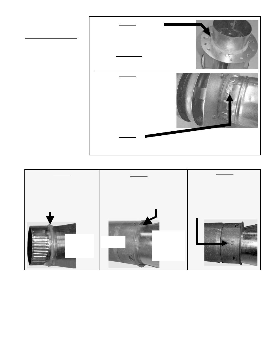
Figure 4B - STEP 1
On the single-wall or Category III
vent pipe or the taper-type reducer,
place a continual 1/4” bead of sili-
cone sealant around the circumfer-
ence.
Figure 4B - STEP 2
Insert the pipe with the bead of sealant
into the inner pipe of the double-wall
pipe until the bead of sealant contacts
the inner pipe creating a sealed joint.
Figure 4B - STEP 3
Make this connection a maximum of 6" (152mm) from the concentric adapter box.
Double-
Wall Pipe
Single-wall
or Category
III vent pipe
or taper-type
reducer
Spaced equally around the double-
wall pipe, drill three small holes
below the sealant ring. Insert 3/4
inch long sheetmetal screws to
secure the joint.
Do not overtighten screws.
Do STEP 2
immediately
following
STEP 1.
NOTE: The double-wall
vent terminal pipe does not
attach to the concentric
adapter box and must be
supported during installa-
tion.
7) Clearance
Do not enclose the vent pipe or place pipe closer than 6" (152mm) to combustible
material.