0 mechanical (cont'd) – Reznor CAUA Unit Installation Manual User Manual
Page 32
Form I-CAUA, P/N 164771 R8, Page 32
6.0 Mechanical
(cont'd)
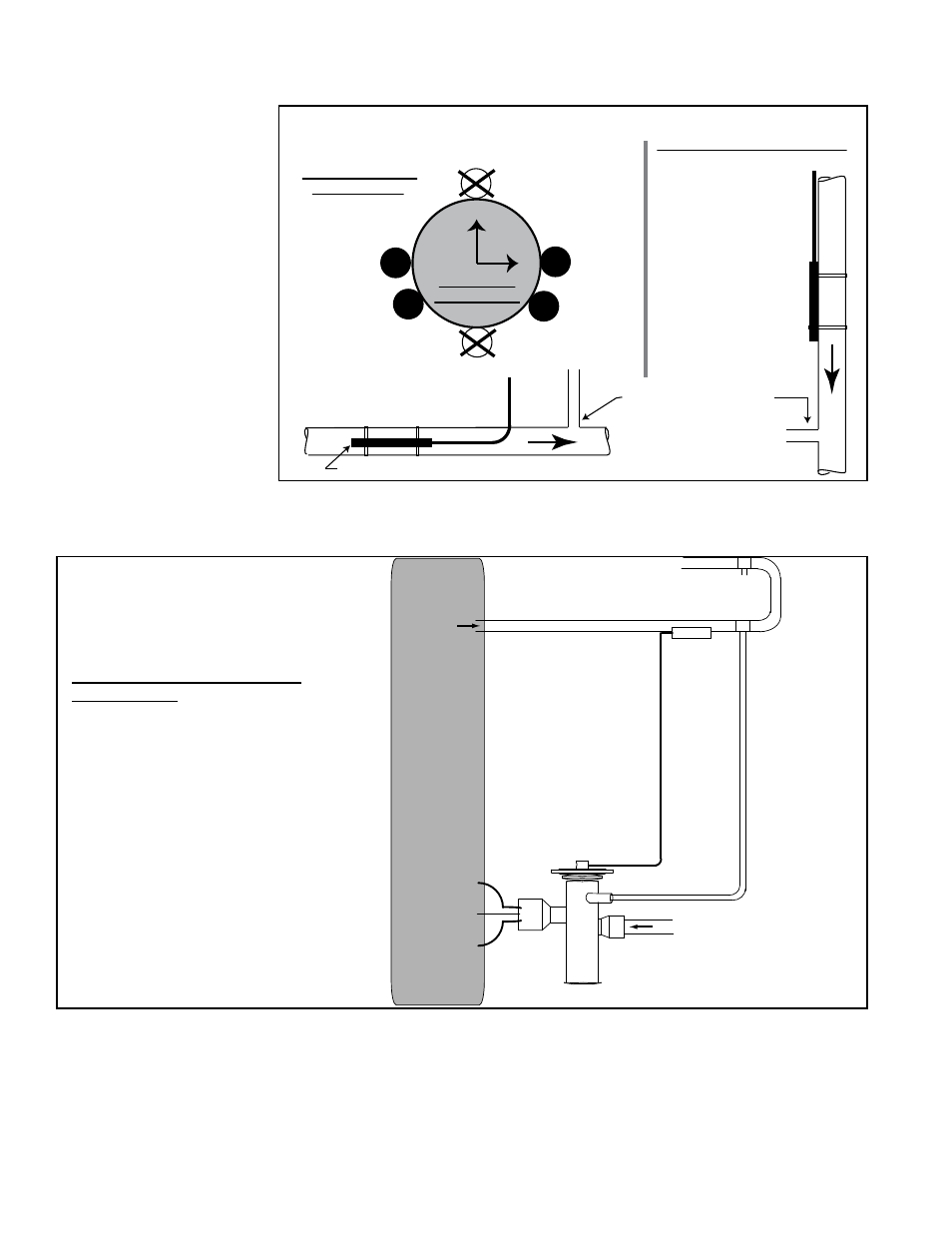
Bulb at
3 o’clock
Bulb at
4 o’clock
Bulb at
8 o’clock
Bulb at
9 o’clock
12
3
6
9
Position bulb flat against the surface of the suction line tubing. Secure bulb
tightly and insulate.
Suction Line
Cross Section
Suction Line
Thermostatic Expansion Valve Bulb
Suction Line
Thermostatic
Expansion
Valve Bulb
(Capillary tube should
be out the top.)
Horizontal Section
of Suction Line
(preferred location)
Vertical Section of Suction Line
(descending flow only)
Capillary
tubing
from TEV
Capillary tubing from TEV
Connect field-supplied
equalizer tubing from the TEV
(FIGURE 25B) into the
suction line a short
distance downstream
of the bulb.
6.6 Cased Cooling Coil, Model ACUA, ACUB, or ACUC or
Option C (cont'd)
FIGURE 25A -
Suction Line
showing Orientation
and Location of
the Thermostatic
Expansion Valve
Bulb and the Equalizer
Tubing
(applies to each circuit)
Thermostatic Expansion Valve
Equalizer Line - To ensure that
the correct pressure is signaled
to the valve, an external equalizer
line must be connected into the
suction line downstream of the
thermostatic expansion valve
bulb. (See location indicated in
FIGURES 25A and 25B.)
Connect the other end of the
equalizer tubing to the 1/4" ODF
stem on the thermostatic expansion
valve as shown in
FIGURE 25B.
FIGURE 25B - Thermostatic
Expansion Valve with External
Equalizer Line Fitting
(required for each circuit)
External equalizer
line requires field-
supplied tubing
from the 1/4” ODF
fitting on the valve
and connected
into the suction
line preferably at
location “X” down-
stream of the
TEV bulb. If “X” is
not possible,
location “Y” is
acceptable as long
as pressure is
essentially the
same as at “X”.
Thermostatic
Expansion
Valve (TEV)
Evaporator Coil in Model
ACU or Option C
Cased Cooling Coil
TEV Bulb
Suction Line
X
Y
Cased Cooling Coil
Drain Line
The cased coil has a 3/4" FPT drain connection. Install a trap (see below) and pitch
the drain line downward at least 1/2" (13mm) for every 10 feet (3M) of horizontal run.
Drain lines must not interfere with access panels. An obstruction in the drain or a poorly
designed drain can cause an over flow. Overflow could result in unit or building dam-
age.
Connect the burner condensate tubing into the cooling coil drain line and continue into
a sanitary drain system.
In addition, an external equalizer line must be installed from the stem on the valve to
a location on the suction line that is downstream of the bulb. Follow the instructions in
FIGURE 25B to install the field-provided tubing.