Control surface throws, Channel radio setup, Channel radio set-up – Great Planes PT-40 MkII Kit - GPMA0118 User Manual
Page 52
❏
3. Check the direction of all control functions. They must
all move in the direction shown in the following sketches. If
not, change the position of the reversing switches on your
transmitter.
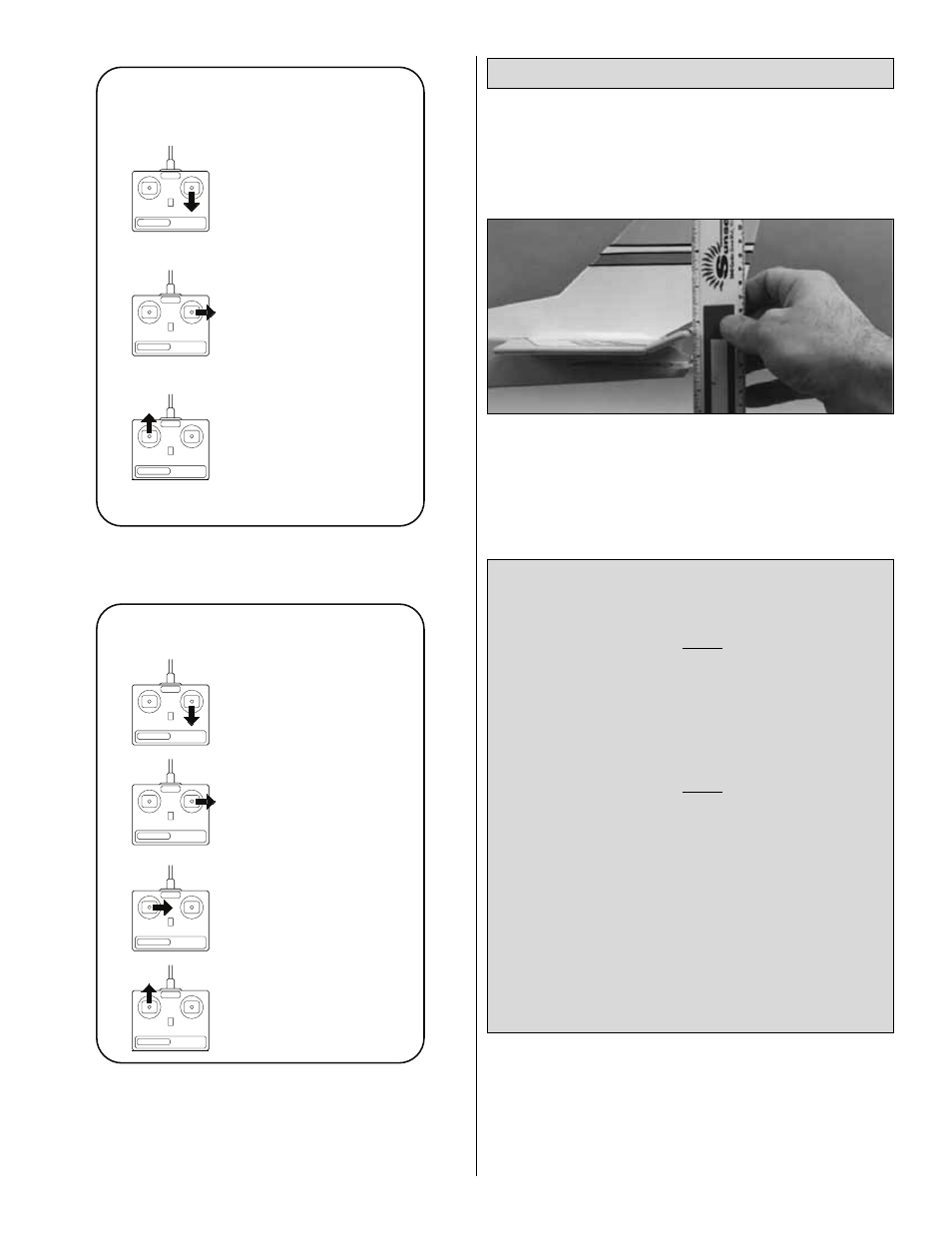
We recommend the following Control Surface Throws:
Note: Control throw (movement) is measured at the trailing
edge of the elevator, rudder, and ailerons.
Note:
If your radio system does not feature Adjustable
Travel Volume (ATV’s), you will have to mechanically adjust
control surface throw. See the following instructions.
SINGLE RATE TRANSMITTER
The following throws are for a transmitter that does not
have Dual Rates.
PT-20
ELEVATOR
1/4" up
1/4" down
RUDDER
1/4" right
1/4" left
AILERONS
1/2"up
1/4" down
PT-40
ELEVATOR
1/4" up
1/4" down
RUDDER
1/4" right
1/4" left
AILERONS
7/16"up
1/4" down
Note: The balance and control throws for the PT have
been thoroughly tested and represent the settings at
which the PT flies best. Please set up your PT to the
specifications listed. If, after a few flights, you would
like to adjust the throws to suit your taste, that’s fine.
Remember, “
more is not better.”
Control Surface Throws
CARBURETOR WIDE OPEN
NOSE WHEEL TURNS RIGHT
RUDDER MOVES RIGHT
LEFT AILERON MOVES DOWN
RIGHT AILERON MOVES UP
ELEVATOR MOVES UP
4-CHANNEL
TRANSMITTER
(STANDARD MODE 2)
4-CHANNEL RADIO SETUP
TRANSMITTER
4-CHANNEL
TRANSMITTER
4-CHANNEL
TRANSMITTER
4-CHANNEL
NOSEWHEEL MOVES RIGHT
CARBURETOR WIDE OPEN
RUDDER MOVES RIGHT
ELEVATOR MOVES UP
4-CHANNEL
TRANSMITTER
(STANDARD MODE 2)
3-CHANNEL RADIO SET-UP
TRANSMITTER
4-CHANNEL
TRANSMITTER
4-CHANNEL
52