Install the engine – Great Planes PT-40 MkII Kit - GPMA0118 User Manual
Page 21
❏
4. Glue in the LG blocks with 30-minute epoxy. Wedge a
scrap balsa stick between the blocks to hold them in
position while the epoxy cures. For added clamping power,
turn the fuselage over and place weights on top of the LG
rail to hold it down.
❏
5. After the epoxy has cured, glue the front and aft fuse
bottoms to the LG rail with medium CA.
❏
6. For this step, the epoxy must be fully cured. Fit the
die-cut 1/8" plywood landing gear drill guide into the
groove in the rail (it doesn’t matter which way it goes in).
Drill a 3/32" pilot hole through the rails and landing gear
blocks at each of the punch marks on the guide. Use care
to drill the holes perpendicular to the fuse bottom. Look
inside the fuse to make sure you drilled the holes straight
into the hardwood blocks.
❏
7. Remove the drill guide, then redrill the holes with a
3/16" bit (5/32" if you are building the PT-20) making
angular adjustments if necessary. Hint: If you have a
numbered drill set, you may drill the holes with a #12 drill bit
(#22 for the PT-20) for easier installation of the landing gear.
❏
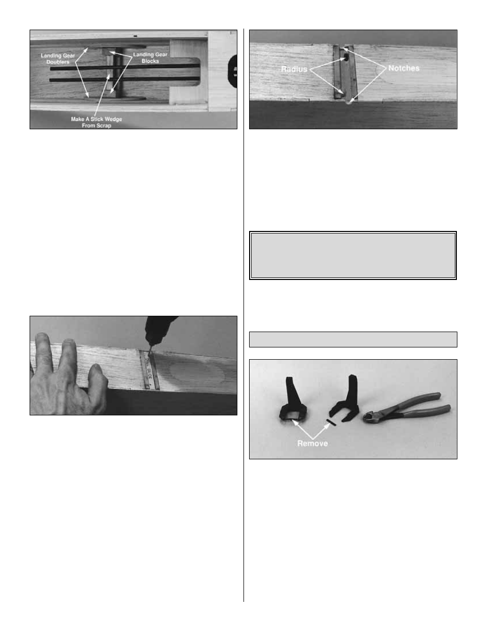
8. Carve a radius in each LG rail hole toward the center
of the fuse to allow the LG wire to fully seat in the holes.
Cut a round notch in each fuse side to clear the LG. Test fit
the main landing gear. It’s helpful if you use a file to
remove any burrs or sharp edges from the ends of the wire.
After fitting the LG in position, you may remove it and set it
aside until final assembly.
❏
1. Remove the “spreader bar” from each mount half.
Carefully trim any extra material left by the spreader bar or
flashing from any other rough edges so the mount halves
will fit together. Fit the mount halves together.
❏
2. Remove the fuel compartment hatch. Use a pen and a
straightedge to mark the vertical centerline on the firewall
by drawing a line connecting the punch marks on the top
and bottom of the firewall.
❏
3. Temporarily bolt the engine mount to the firewall using
four 6-32 x 1" screws with #6 flat washers (use 4-40 x 1"
screws with #4 washers if you are building the PT-20). Don’t
tighten the screws completely until after the engine has
been positioned.
Install the Engine
Note: If you will be installing a 4-stroke engine you need
to plan ahead for servo location and pushrod routing.
Refer to the sketch on page 46 and the fuselage plans
for the 2-stroke/4-stroke servo and pushrod setup.
21