Expert tip – Great Planes PT-40 MkII Kit - GPMA0118 User Manual
Page 22
Note: You will need your engine for the following steps.
From here on it is a good idea to plug the holes in your
engine so balsa dust cannot get in. Stuff a piece of paper
towel into the exhaust and carburetor venturi to seal
them off.
❏
4. Remove the needle valve from your engine. Position
the engine on the engine mount and adjust the engine
mount halves until the engine mounting lugs will sit flat on
the rails. Position the mount so the firewall centerline is
centered between the “tick” marks on the mount. Tighten
the screws to hold the mount firmly in position against
the firewall.
❏
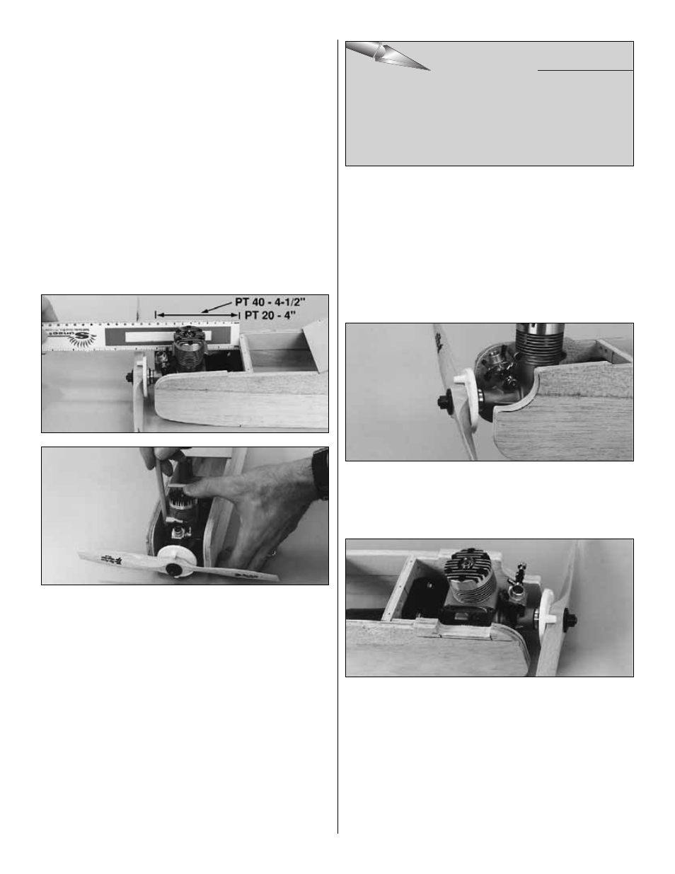
5. Mount the spinner back plate on your engine. If you’re
building the PT-40 position the engine so that the spinner
backplate is 4-1/2" (115mm) from the firewall. If you’re
building the PT-20, position the engine so that the spinner
pack plate is 4" (102mm) from the firewall. Carefully mark
the engine mounting holes on the rails with a sharpened
piece of wire or a pencil. Note: If installing a 4-stroke
engine, the engine may be forward of the recommended
position to allow for the choke mechanism. This is
acceptable and will not cause a balance problem.
❏
6. Remove the engine and engine mount from the fuse.
Use a center punch or sharpened nail to "dimple" the marks
on the rails, then drill a 3/32" hole through the rails at each
punch mark. If you have access to a drill press, this is the
best tool for the job. However, if you are using a hand-held
electric drill, try to keep the bit perpendicular to the rails.
❏
7. Install a threaded ball stud in the bottom hole of the
carburetor arm of your engine and secure it with a 0-80 nut
and a drop of epoxy or thread locking compound. Fasten
the engine to the mount with four #4 x 5/8" screws
included in this kit (or your 4-40 screws). Hint: Add a drop
of household oil to the #4 sheet metal screws to make them
easier to screw into the mount.
❏
8. Carefully and neatly cut away some of the fuselage
side so you can reach the needle valve. A Dremel tool with
a sanding drum works well for this.
❏
9. Remove some of the fuselage side to clear the
muffler. There should be approximately 1/8" clearance
between the muffler and the fuselage.
❏
10. From one of the leftover pieces of outer pushrod
tube (you saved from the elevator and rudder guide tubes)
cut a piece for the throttle guide tube. It should extend
1/2" past the firewall and 1/2" aft of F-2. Temporarily install
the throttle guide tube through the holes in the firewall
and F-2.
EXPERT TIP
EXPERT TIP
EXPERT TIP
22
Some modelers prefer to secure the engine to the mount
with machine screws (not supplied) because they are
easier to screw in. For both the PT-20 and 40, 4-40 x 3/4"
screws are recommended. Use a #48 drill bit to drill the
holes, then tap the threads with a 4-40 tap.