Great Planes PT-40 MkII Kit - GPMA0118 User Manual
Page 49
❏
3. Snap a nylon Faslink
™
onto both pushrods and cut off
the excess wire 1/16" above the Faslink. Caution: Wear
safety glasses whenever you cut wire! If you have
removed the pushrods to bend and cut the wire, unscrew
the clevis from the threaded end. Slide the pushrods back
into the guide tubes from the front and screw the clevises
back on.
❏
4. Remove the Faslink and temporarily inser t the
pushrods through the second from the outside hole in both
servo arms (this position may change upon setting the
throws). Reinstall the Faslinks to securely connect the
pushrods to the servos.
❏
5. Adjust the clevises so the elevator and rudder are
neutral with the radio on, the servos centered and the
pushrods connected.
❏
6. If you haven’t already done so, insert the nose wheel
steering pushrod into the Screw-Lock Pushrod Connector,
then center the nose wheel (remember the steering arm
should be angled forward). Install a 4-40 x 1/8" socket
head screw in the connector and tighten it down. Test the
steering. When the rudder moves to the right, the nose
wheel should also move to the right. Make sure the nose
gear steering arm does not contact the firewall when the
rudder stick is pushed fully to the left.
❏
7. Once you have finished setting up the nose wheel
steering, snap the nylon retainer on the connector under
the servo horn. Remove the 4-40 screw, then reinstall it
with thread locking compound and tighten it down. Cut off
the excess wire, leaving about 1/2" sticking out of the
connector.
❏
8. Snap the nylon ball link at the front of the throttle
pushrod onto the metal ball previously installed on the
carburetor arm. Pull the throttle control stick and trim lever
on your transmitter to the fully “back” or closed position.
❏
9. See the photo at step 4, then insert the pushrod
through the Screw-Lock Pushrod Connector if you haven’t
already done so. Install the horn on the servo so it points
toward the tail of the model at about a 30-degree angle as
shown.
❏
10. Pull the throttle pushrod toward the tail to fully close
the throttle. Install a 4-40 x 1/8" socket head screw in the
connector and tighten it. Move the throttle trim lever and
watch the carburetor to see if it opens slightly. If the servo
does not move (just sits there buzzing), flip the “Servo
Reversing Switch” on your transmitter. Open the throttle all
the way with the main control stick. If the throttle opens all
the way but the pushrod bends (or the servo buzzes), move
the connector one hole in toward the center of the servo
horn to decrease the amount of throw.
The goal is to get the engine to idle as slowly (but reliably)
as possible with the throttle stick pulled all the way back
and the trim switch in the mid to full open position. To shut
the engine off, simply pull back the trim switch. This
prevents you from inadvertently shutting the engine off
during flight.
❏
11. When the throttle works properly, install the nylon
retainer on the bottom of the screw lock connector to
secure it. Tighten the screw (with thread lock) and install
the servo horn screw. Cut off the extra wire, leaving about
1/2" behind the connector.
❏
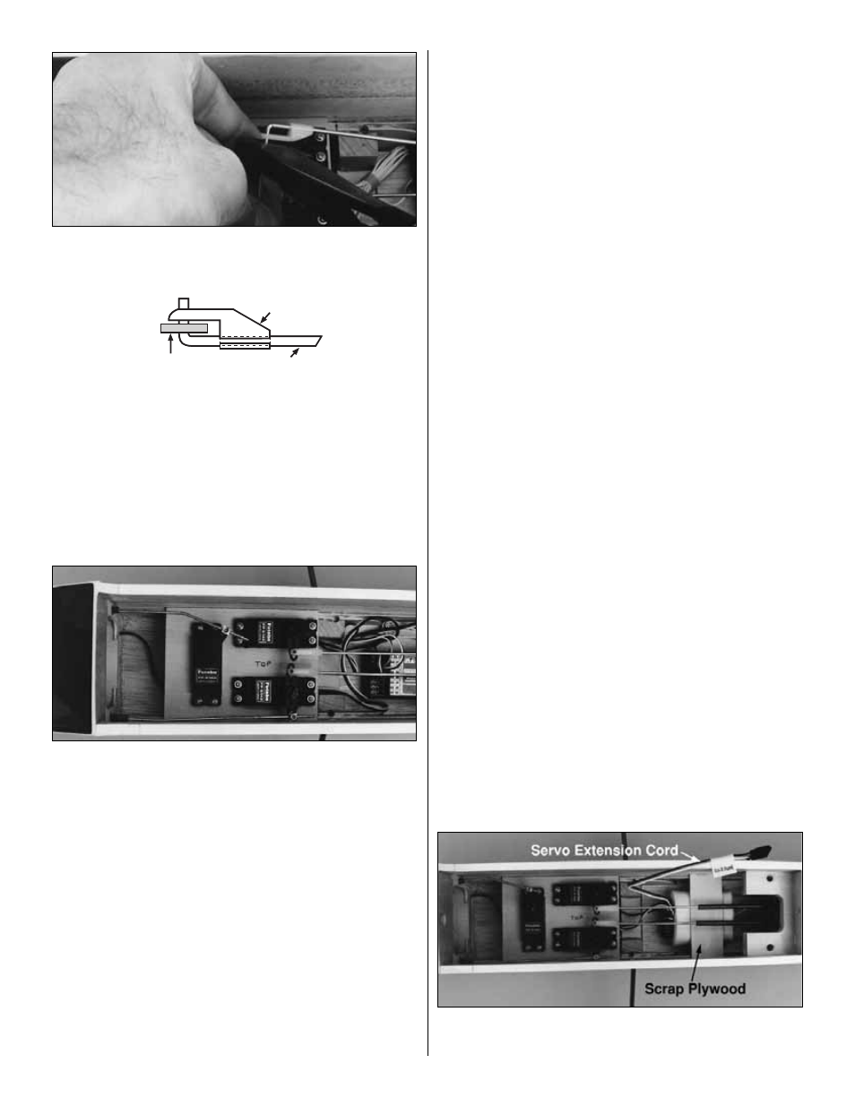
12. If you have a servo extension cord and are using
ailerons, plug it into to the receiver. A servo extension cord
will allow you to easily connect the aileron servo to the
receiver when you install the wing for each flying session.
❏
13. Wrap your receiver with 1/4" thick foam rubber.
Secure the foam with a couple of rubber bands or tape.
FasLink
2-56 (.074") Pushrod Wire
Servo Horn
49