Great Planes PT-40 MkII Kit - GPMA0118 User Manual
Page 46
❏
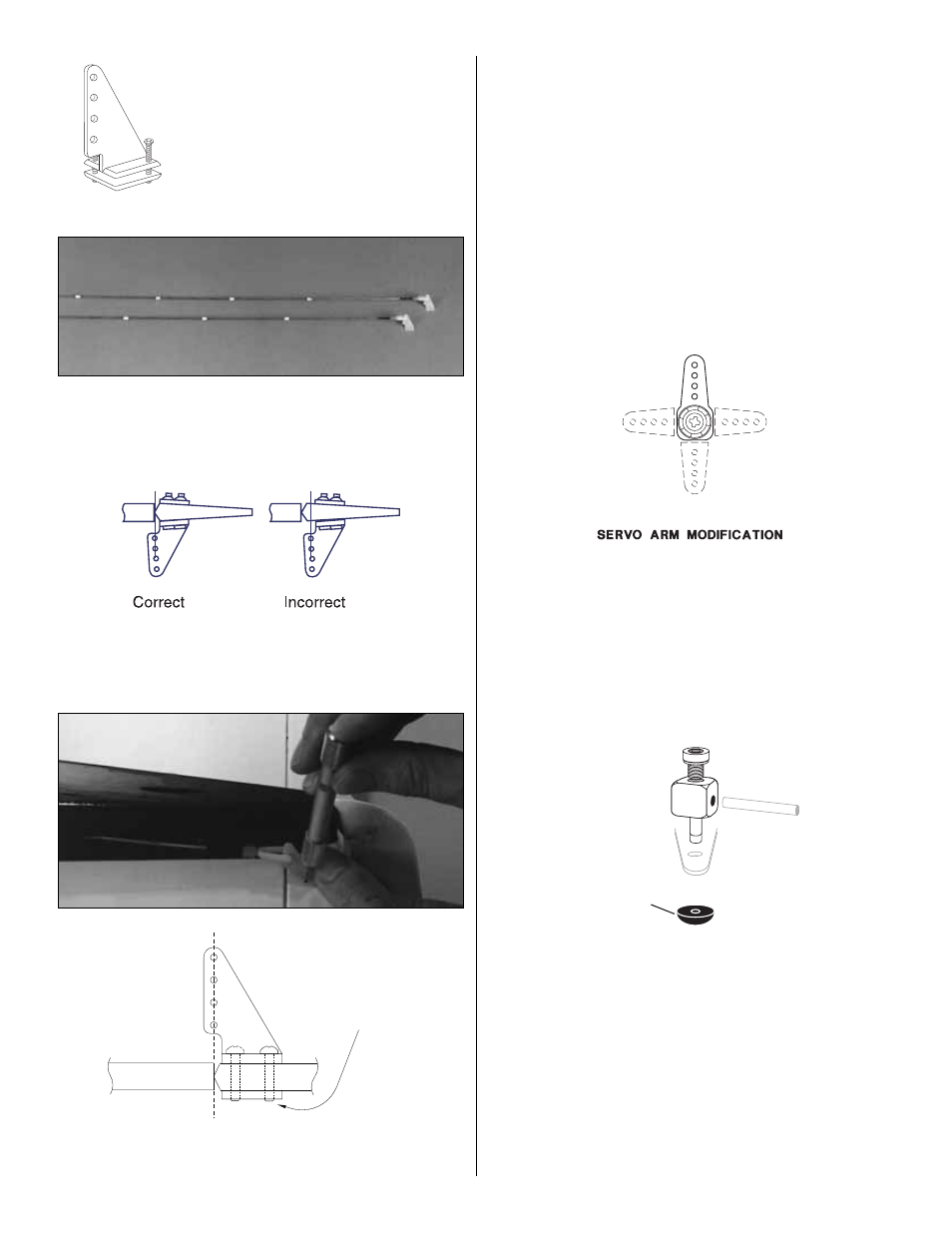
9. Trim the backing plate from a nylon control horn,
then temporarily fasten the clevis to the second from the
outer hole of the horn. Make a second pushrod assembly
exactly the same as the first.
❏
10. Insert the pushrods into the tubes in the fuse, then
hold the horn on the elevator aligned as shown in the
sketch. The rudder horn is on the left side of the airplane
and the elevator is on the right.
❏ ❏
11. Mark the location of the holes on the elevator or
use the holes themselves in the horn as a guide to drill
3/32" holes through the control surface. Screw the horn in
place with two 2-56 screws and the backing plate. Repeat
for the rudder.
❏
12. Prepare three “cross” style servo horns as follows
but don’t install them on the servos until instructed to do so:
Note:
The size and shape of servo horns varies from
manufacturer to manufacturer. The sketches and photos
show a typical radio installation with standard horns. All
standard servo horns should fit in the PT-40. If you are
building the PT-20 some servo horns may interfere with
each other or the side of the fuselage. To avoid this, shorten
the servo horns and move the pushrod one hole in or, if you
have a Futaba radio system, you can make the horns out of
the “six arm” horns which are shorter.
❏
A. Cut off three arms from two servo horns included with
your radio control set to make them into “one arm” servo
horns. These two single arm horns will be used for the
elevator and throttle. Use your bar sander to remove the
remaining jagged edges left from the cut-off arms.
❏
B. Enlarge the holes in one of the horns with a 5/64"
drill. This will be the elevator horn. The other horn is the
throttle horn.
❏
C. Temporar ily install a Screw-Lock Pushrod
Connector
™
in the throttle horn where shown on the plan.
Don’t install the retainer until you test the throttle’s
operation.
❏
D. Cut the opposite arms off a third servo horn to make
one “long arm” horn. This is the rudder horn.
❏
E. Enlarge the holes in only one side of the rudder
horn with a 5/64" drill. Install another Screw-Lock Pushrod
Connector without the retainer on the arm with the small
holes where shown on the plan. This is where your nose
wheel steering pushrod will attach.
RETAINER
Trim off the excess
screw threads
GP
46
Nylon Control Horn