Great Planes PT-40 MkII Kit - GPMA0118 User Manual
Page 50
Position the receiver where it was when you balanced the
model, then glue a scrap piece of plywood to the fuselage
sides over the receiver to hold it in position.
❏
14. Route the receiver antenna through the optional
antenna tube along the bottom of the fuse or to the top of
the fin as shown on the plans. Secure the rudder and
elevator servo horns with the screws included with the radio
control set.
❏
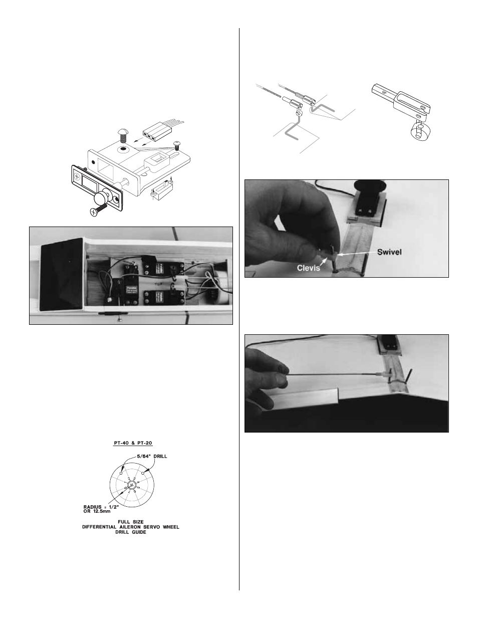
15. Mount the receiver switch and charging jack through
the fuselage on the opposite side of the muffler exhaust
with a Great Planes Switch and Charge Jack Mounting
Set (GPMM1000). Make sure the switch and switch
mount will not interfere with the aileron servo and
pushrods or any of the other components.
Note:
If you will be using only 3 channels without functional
ailerons, skip ahead to Aileron Lock for 3-Channel
Operation.
❏
16. Drill two 5/64" holes in the aileron servo wheel as
shown on the plan. The forward placement of the holes will
cause the ailerons to have “differential” travel. This means
that they won’t move down as much as up – an aid to
making smooth turns. See the definition of “Adverse Yaw”
and “Differential Throw” under “Some Modeling Terms
and Trivia.”
❏
17. Snap a nylon Swivel into a Nylon Swivel Clevis.
Use the clevis to screw the swivel onto an aileron torque
rod to the position shown on the plan.
❏
18. Put an “L” bend in the last 1/4" of the unthreaded end
of a 6" threaded rod and use the “L” as a “handle” to screw
the rod about 14 revolutions into the clevis. Cut off the bent
portion off the rod. Repeat the same operation to install the
other swivel, swivel clevis, and 6" threaded rod onto the
other torque rod.
❏
19. Plug the aileron servo into your receiver, then center
it as you have done with the other controls.
❏
20. While holding the ailerons so they are neutral, mark
both pushrods directly over their respective holes in the servo
wheel. Remove the pushrods by unsnapping the clevises.
50
Switch & Charge Jack
Mounting Set