Great Planes PT-40 MkII Kit - GPMA0118 User Manual
Page 30
❏
6. You will need something to prop up one of your wing
tips to set the correct dihedral angle (see the photo at step 16).
Use the chart that follows to determine how much to raise
one of the wing tips for the model you are building. You can
use a stack of books, balsa blocks or something similar for
this job:
PT-20
PT-40
A-wing
7" (178mm)
8" (204mm)
B-wing
4-3/8" (112mm)
5" (128mm)
❏
7. Lay two 1' sheets of waxed paper on your work table
and have a few sheets of paper towel on hand to wipe
your hands.
❏
8. Coat the ends of the LE’s, main spars and webs, TE’s
of both wing panels, both center joiners and both sides of
the webs in each wing panel with 30-minute epoxy. Lay the
CJ’s (epoxy side up) on one of the sheets of waxed paper
so you don’t mess up your work table.
❏
9. Install the center joiners in one wing panel just as you
did when you were test fitting. Join the other wing panel to
the assembly with the center joiners.
❏
10. Lay one wing panel on your flat building table with
the other sheet of waxed paper under the panel. Lay the
wing tip of the other wing panel on the stack of books or
blocks to set the correct dihedral angle (see step 16).
❏
11. Align the TE and LE. Then pin them together. Clamp
the wing halves together by placing small C-clamps on the
center joiners of each wing panel.
❏
12. Wipe away excess epoxy with a paper towel, double
check all the glue joints, then let the epoxy cure fully before
proceeding.
❏
13. After the epoxy from the preceding step has cured,
remove the clamps and T-pins. Coat one side of the
remaining joiners with 30-minute epoxy. Place the joiners
epoxy side up on the sheet of waxed paper so you don’t
mess up your work table. Immediately proceed to the next step.
❏
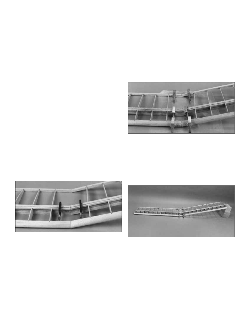
14. Position the forward joiner and the aft joiner on the
front and rear of the main spars respectively (on the PT-40
there is a small space between the center joiners and the
forward and aft joiner). Make sure the aft joiner is centered
above and below the main spars for the wing sheeting and
the top edge of the forward joiner is fully contacting the
bottom of the forward spar. Clamp the joiners in position.
Proceed immediately to the next step.
❏
15. Clamp the leading edge joiner and the trailing edge
joiner to the leading and trailing edge. Make sure both
joiners are centered between the top and bottom of the
trailing and leading edges for the wing sheeting.
❏
16. Use a balsa stick to wipe away excess epoxy that
was squeezed out from the top and bottom edges of all the
joiners. Confirm that the joiners have not shifted and are
still centered above and below the LE’s, TE’s and spars.
Place the wing back onto your work table with one of the
panels propped up. Do not disturb the wing until the epoxy
has fully cured.
Here’s your chance to get some sleep, so rest while you
can. There’s still lots more to do!
30