Checks and final setup, Aileron lock for 3-channel operation – Great Planes PT-40 MkII Kit - GPMA0118 User Manual
Page 51
❏
21. Make Z-bends in the pushrods, then cut off the
excess pushrod material. Fit the pushrods through the top
of the servo wheel and make a slight bend in the pushrods
as shown in the sketch and on the plan. Mount the servo
wheel to the servo, then adjust the clevises so the ailerons
will be centered when the servo is centered. Connect the
clevises to the torque rods.
❏
1. See the photo at step 17, then snap a Nylon Swivel
into a Nylon Swivel Clevis. Use the clevis to screw the
swivel onto an aileron torque rod so that 1/4" of thread
protrudes below the top of the swivel.
❏
2. See the photo at step 18, then put an “L” bend in the
last 1/2" of the non-threaded end of a 6" threaded rod. Use
the “L” as a “handle” to screw the rod about 14 revolutions
into the clevis. Cut off the bent portion off the rod. Repeat
the same operation to install the other Swivel, Swivel Clevis
and 6" threaded rod onto the other torque rod.
❏
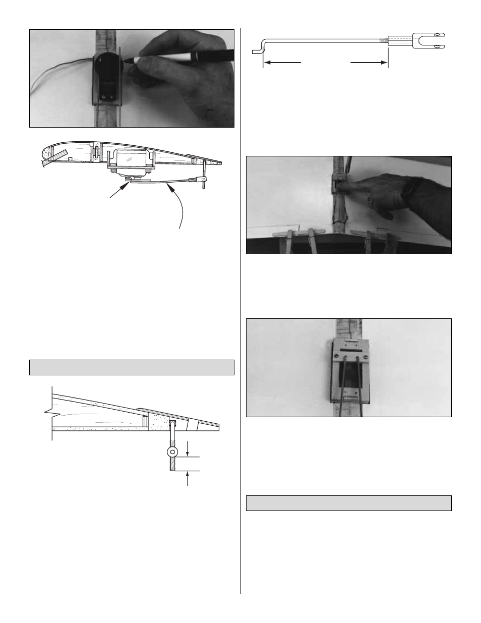
3. If you are building the PT-40, mark the wire pushrods
4-1/2" from the back end of both clevises (3-7/8" for the
PT-20). Make Z-bends at the mark on both pushrods.
❏
4. Drill two 5/64" holes through the punch marks on the
die-cut 1/8" plywood aileron lock. Insert the Z-bends into
these holes.
❏
5. Temporarily lock both ailerons in position with popsicle
sticks and clothespins as shown. Position the aileron lock on
the aileron servo tray. Drill a 1/16" hole through both ends of
the aileron lock into the sides of the servo tray. Enlarge the
holes in only the aileron lock with a 3/32" drill bit.
❏
6. Use two #2 x 3/8" screws to secure the aileron lock to
the servo tray. Remove the popsicle sticks and clothespins.
If you decide to install a servo at a later date, simply install
the servo in place of the aileron lock. The location of the
Z-bends should work with most servos to provide the
correct setup.
❏
1. IMPORTANT: Go back and check your installation. Be
sure that all servo screws, horns and other components are
secure. Confirm that you have installed the retainers on the
Screw-Lock Pushrod Connectors.
❏
2. Apply a strip of 1/16" thick foam wing-seating tape to
the wing saddle. This tape provides a seal against dirt and
exhaust oil, and cushions the wing from vibration.
Checks and Final Setup
PT-40 4-1/2"
PT-20 3-7/8"
1/4"
Aileron Lock for 3-Channel Operation
Aileron Pushrods must
be inserted from the top
of the servo wheel
A slight bend here
is acceptable
51