Preliminary radio installation, Install the landing gear – Great Planes PT-40 MkII Kit - GPMA0118 User Manual
Page 44
❏
7. Prepare the hinge slots in the ailerons the same way
as the tail surfaces.
❏
8. Use a toothpick to pack the torque rod holes in the
ailerons with 30-minute epoxy, then install the ailerons with
the hinges and thin CA using the methods we’ve described.
Wipe away the epoxy that is squeezed out of the ailerons
with a paper towel and alcohol.
❏
9. If you’re building the rubber band-on wing, reinstall the
1/4" wing dowels and glue them in position with thin CA.
Fuelproof the exposed ends of the dowels.
Skip step #1 if you are building the PT-20
❏
1. Enlarge the wheel hub axle holes of the PT-40 main
wheels only with a #10 (or 13/64") drill bit and an electric drill.
❏
2. Temporarily install the main wheels on the main
landing gear using a wheel collar (not included) on each
side of the wheel.
❏
3. Note where the set screw of the outer wheel collar
contacts the landing gear wire (usually there is a mark on
the wire where the set screw was tightened). Remove the
wheel collar, then file a flat spot where the set screw
contacts the gear. This is only required for the outer wheel
collars that hold the wheels on.
❏
4. Reinstall the wheel and wheel collar. Use liquid thread
lock to secure the set screws on all wheel collars.
❏
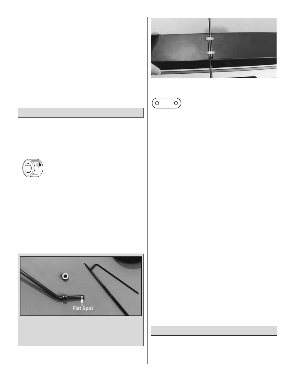
5. Seat the landing gear wire in the landing gear rail on
the fuselage. Use a nylon landing gear strap as a guide
to drill 1/16" pilot holes for the screws. Secure the landing
gear with two nylon straps and four #2 x 3/8" sheet
metal screws.
❏
6. Install the nose wheel on the nose gear wire with two
3/16" wheel collars. Don’t forget the flat spot for the outer
collar and thread lock on the set screws.
❏
7. Roughen the outside surface of the throttle and nose
steering pushrod guide tubes. Install the tubes in the
firewall and F2, then glue them in position with medium CA.
❏
8. Reinstall the engine mount, the nose landing gear
wire, the nose steering pushrod, the steering arm and the
throttle pushrod the same way you did during fuselage
construction. Check that the nose gear spring coil clears
the bottom of the fuse, then temporarily tighten the set
screw in the wheel collar under the engine mount to set the
height of the nose gear wire.
❏
9. Refer to the top view of the fuse plan for the required
angle of the nose wheel and the steering arm, then
temporarily tighten the screw in the steering arm. This
off-center position will enable you to turn left, as well as
right. Test the linkage for free movement. The collar and
steering arm will be securely locked in position later when
we check the ground stance of the model.
❏
10. Install the engine, muffler, prop and spinner. Don’t
worry about putting the prop and spinner on permanently at
this stage.
❏
1. Test fit your servos in the die-cut 1/8" plywood servo
tray and make adjustments to the size of the openings for
the servos if required. The sides of the servos should not
contact the edges of the openings in the tray.
Preliminary Radio Installation
A flat spot is required to provide more surface for the set
screw to hold onto. Locate the mark left by the set screw.
Now, with the mark facing up, use a flat file or a Dremel
tool with a narrow grinding wheel to make a flat spot at
the mark.
Install the Landing Gear
44
Wheel Collar
Nylon Landing Gear Strap