Join the fuselage sides – Great Planes PT-40 MkII Kit - GPMA0118 User Manual
Page 17
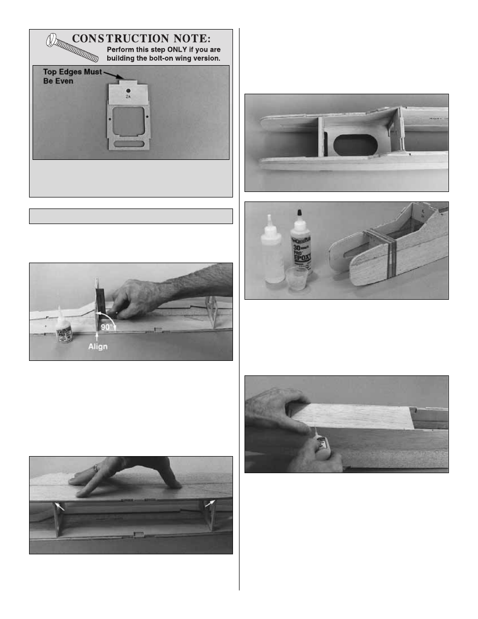
IMPORTANT: Position all of the formers with the embossed
numbers facing the front of the model.
❏
1. Test fit the die-cut 1/8" plywood formers F-2 and F-3 in
position on the right and left fuse sides. Be sure the
bottoms of the formers line up with the bottom of the
doublers on both fuselage sides.
For the bolt-on wing
version, the F-2A former must face toward the front of the
model. Glue F-2 and F-3 to the right fuse side as shown
with medium CA. Hold F-2 and F-3 vertical with a triangle
or building square while the CA cures.
❏
2. Glue the left fuse side to formers F-2 and F-3,
making sure the fuse sides are aligned and the bottoms of
the formers are flush with the bottom of the doublers.
❏
3. Test fit, but do not glue, the die-cut 1/8" plywood tank
floor and the firewall assembly between the fuse sides. The
tab at the rear end of the tank floor should fit into the notch
at the bottom of F-2 and the front of the tank floor should fit
under F-1C on the back of the firewall assembly. Make any
adjustments if required to the firewall sides or the tank floor.
❏
4. With the tank floor installed (but not yet glued), glue
the firewall assembly in position with 30-minute epoxy.
Use rubber bands and/or masking tape to clamp the
fuselage sides together while the epoxy cures. After the
epoxy has cured, glue the tank floor in position with
medium CA.
❏
5. Test fit the die-cut 3/32" balsa front fuse bottom into
the notches and recess on the bottom of the fuse. If you
have your battery pack handy, simulate installing it under
the tank floor as you would if the model was completed. A
500 mAh flat pack wrapped in foam will fit but if you have a
larger battery pack you may wish to enlarge the opening in
the tank floor. Make modifications before you glue the front
fuse bottom in position. When satisfied with the fit, glue the
front fuse bottom in position with thin CA along both outside
edges. Turn the fuse over, then wick thin CA into the inside
joints between the bottom and the formers. Follow with
medium or thick CA in any open joints.
Join the Fuselage Sides
17
❏
16. Glue the die-cut 1/8" plywood former doubler
F-2A to the front of former F-2 (that’s the side with the
punched number) so the top edges are even.