Great Planes PT-40 MkII Kit - GPMA0118 User Manual
Page 16
❏
10. Notice that two pieces of the wing bolt plate
assembly have grain running in one direction while the third
piece has grain running opposite to the first two. The odd
one goes in the center of the “sandwich.” Mix about 1/4 oz.
of 30-minute epoxy and glue the bolt plates together as
shown (the extra epoxy will be used in the next step). This
assembly must be clamped together with C-clamps or
weighted down while the epoxy cures. If you use weights,
be sure the pieces do not slide and shift when you add
the weights.
❏
11. Use the remaining 30-minute epoxy to glue F-1A,
F-1B and F-1C together. Be sure that F-1A (the one with
the punch marks) is on top of the stack with the punch
marks facing outward, the locking tabs are aligned, and
that F-1C is flush with the top edge of the assembly (see
the fuse plan). This assembly must be held together with
clamps, or weighted down while the epoxy cures. Note: If
the three formers are wrapped, simply clamping them
together may not necessarily “cancel out” the warps. It is
best to clamp the assembly over waxed paper to a flat
board or table. Allow the epoxy to fully cure before
removing the clamps.
❏
12. Position the die-cut 1/8" plywood formers F-2
through F-5 over a piece of scrap wood, then drill a 3/16"
hole through each of the punch marks (former F-4 on the
PT-20 is balsa). Do not drill the F-1 assembly during this
step. Note: When punching out former F-2 from the die
sheet, don’t accidentally throw away the plywood hatch
retainer as it may be easily mistaken for scrap. Refer to the
die drawings.
❏
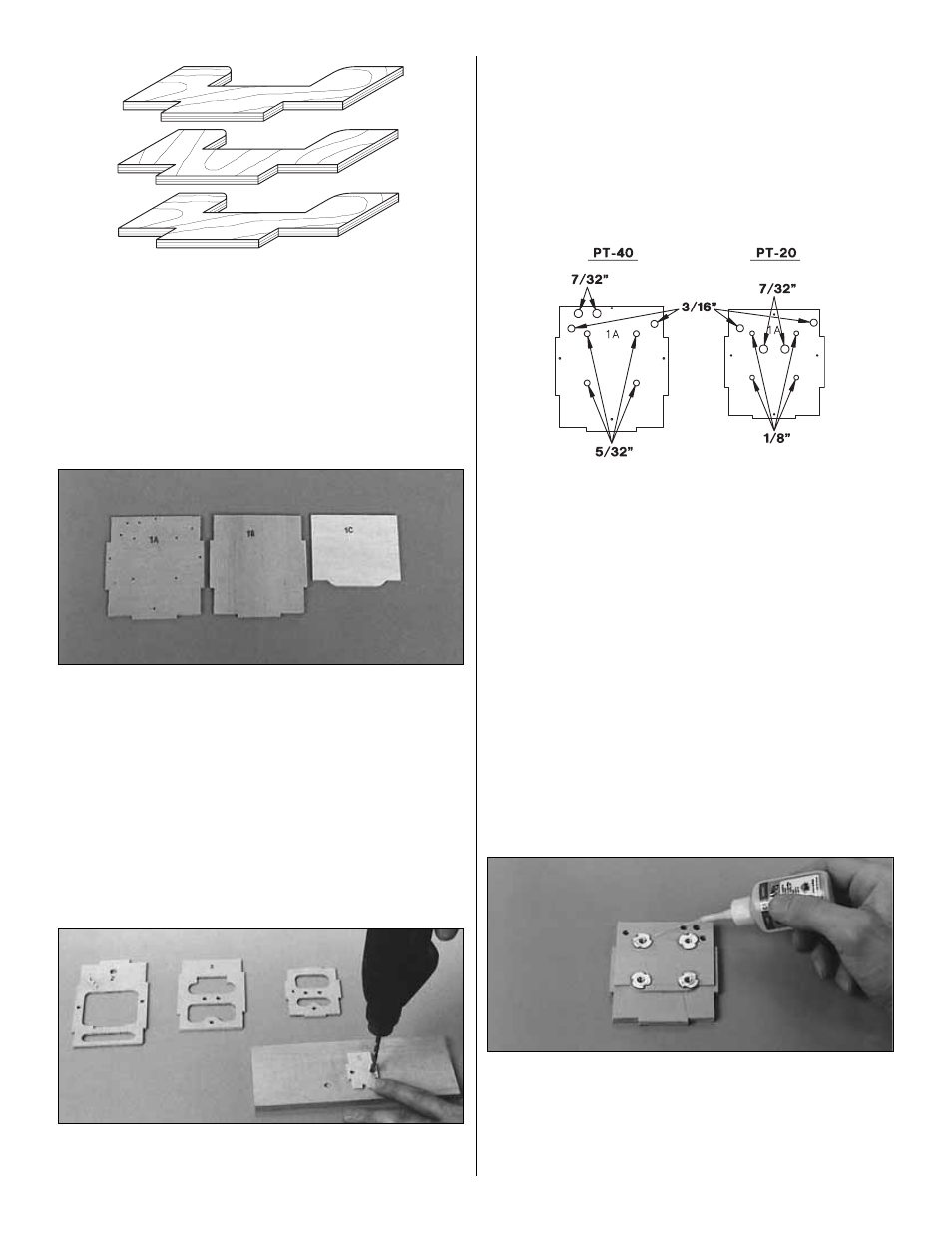
13. Refer to the sketch, then drill two 3/16" pushrod tube
holes through the firewall where indicated. Change your bit
size to 7/32" (or 15/64" for perfection) and drill the two fuel
tube holes where indicated. Finally, drill four 5/32" holes
(1/8" if you’re building the PT-20) for the engine mount blind
nuts. Note: The remaining four punch marks around the
perimeter of the firewall could be used for locating the
center of the firewall should you choose to use a different
engine mount.
❏
14. Clean up any slivers from around the holes you
drilled and also the edges of the formers with a bar sander
and 220-grit sandpaper.
❏
15. Press a 6-32 blind nut (4-40 if you’re building the
PT-20) into one of the holes in the back of the firewall
(F-1C), then tap it gently with a hammer until it is fully
seated. Put a few drops of thin CA on the outer edge of the
flange to secure the blind nut. Install the remaining three
blind nuts the same way.
16