Final radio hook up – Great Planes PT-40 MkII Kit - GPMA0118 User Manual
Page 48
slow down for landing. Moving the balance aft makes the
model more agile, providing it with a lighter and snappier
feel. Please start at the location we recommend and do
not at any time balance your model outside the
recommended range.
❏
2. Mount the wing to the fuselage with rubber bands or
bolts. The engine, muffler and propeller should also be
mounted for the C.G. check.
❏
3. Set the fuel tank (empty) on top of the fuel tank hatch
to simulate the actual weight distribution of the finished
model with the tank installed. With the wing attached to the
fuselage, lift the model with your fingertips at the balance
point. If the tail drops when you lift, the model is “tail heavy”
and you must move the battery and/or the servo tray toward
the nose to achieve balance. If the nose drops, it’s “nose
heavy” and you must move the battery and/or servo tray
toward the tail to achieve balance. The C.G. is always
determined with the fuel tank empty.
❏
4. Balance the model by shifting the receiver battery,
servo tray and receiver, then retesting. When balance is
obtained note the position of the receiver, servo tray and
the battery pack.
❏
5. If the balance cannot be achieved by positioning the
battery, servo tray and receiver, you may add stick-on lead
weight to the tail or nose if required.
❏
6. Once the position of the battery has been determined
confirm that it is securely wrapped in foam and packed in
tight enough under the tank floor so that it cannot shift
during flight or a rough landing.
❏
7 If you haven’t already done so, assemble the fuel tank
according to the manufacturer’s instructions. Connect about
6" of medium silicone fuel line to the “vent” and about 10" of
fuel line to the “pickup” fittings on the tank (most modelers
leave the third “fill” line closed because you can fill the tank
through the pickup line).
❏
8. Cover the tank floor with 1/4" foam rubber. Insert the
tank into the tank compartment as you route the fuel lines
through the holes you drilled in the firewall (you may
temporarily remove the servo tray – or just the throttle
servo). Cut the lines to the proper length and connect them
to the carburetor and muffler pressure fitting.
❏
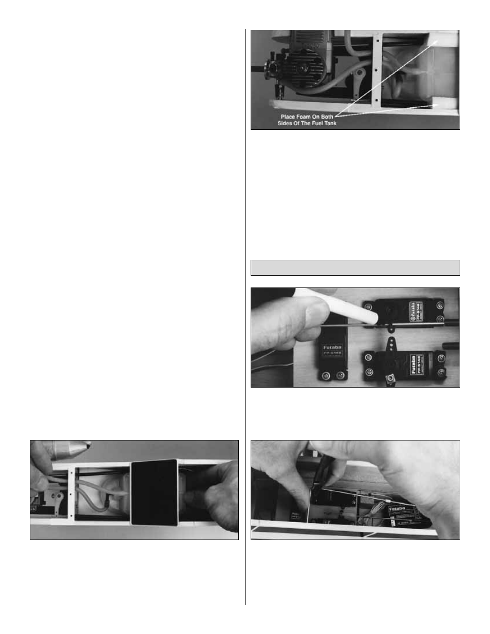
9. Place more foam on the sides and top of the tank.
❏
10. Glue the servo tray securely to the fuse doublers and
fuse sides with medium CA at the position required to
achieve balance.
IMPORTANT: After the model is 100% complete, recheck
the balance.
❏
1. Center the elevator and rudder, then use a felt-tip
pen to mark the pushrods where they cross the holes in the
servo horns.
❏
2. Disconnect the clevises from the horns at the elevator
and rudder. Make a 90-degree bend in the pushrods at the
marks – hold the pliers firmly and try to make a nice, sharp
bend. Hint: You may remove the pushrods from the
fuselage for this step. Remove the pushrods from the guide
tube and bend the wire. Proceed to step 3.
Final Radio Hook Up
48