Attach the stab and fin to the fuse – Great Planes PT-40 MkII Kit - GPMA0118 User Manual
Page 24
❏
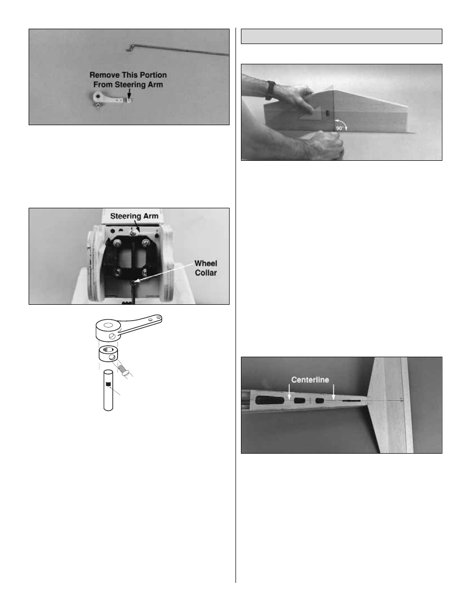
4. Place a 5/32" wheel collar inside the nylon steering
arm and start a 6-32 x 1/4" screw into the arm and the
wheel collar (see the following sketch). Carefully cut the
end off the steering arm so there are only two holes left.
Enlarge the outside hole in the steering arm with a 5/64"
drill bit (#47 for perfection), then insert the nose gear
pushrod wire with the Z-bend into the hole.
❏
5. Slide the nose gear pushrod wire through the guide
tube and place the arm on the nose gear sticking out of the
engine mount. Position the steering arm as shown on the
plan, then temporarily tighten the set screw.
❏
6. Bend the nose steering pushrod away from the
fuselage side about 1" aft of F-2. Test the actuation of the
nose steering by moving the pushrod back and forth from
inside the fuselage. Position the hatch on the fuselage and
confirm that it does not interfere with the Z-bend. If
necessary, make adjustments to the Z-bend or carve a little
material from the hatch to clear the Z-bend.
There, we slipped in a little bit of the control hookups so
that’ll make the finishing procedure move a little faster. Put
all your tools away, dust off your workbench, vacuum the
floor and get ready to glue the tail surfaces to the fuselage.
After you build the wing, all of the wood working will
be complete!
❏
1. Remove the elevator from the stab and measure the
total width of the stab at the TE. Make a mark at the
midpoint of the TE. Use a drafting triangle or a carpenter’s
square to draw an accurate centerline on the top of the
stab at the mark.
❏
2. Accurately measure the width of the fuse at the top of
F-3, and just in front of the stab base, then mark the center
of the fuse top at both of those locations. Lightly draw a
centerline between these two marks (the centerline should
perfectly bisect the slot for the dorsal fin tab). Stick a pin
into the fuse top at the F-3 centerline mark.
❏
3. Temporarily join the elevator to the stab with hinges.
Position the stab and elevator on the stab base with the
centerline of the stab aligned with the centerline of the fuse.
Pin the stab to the fuselage.
❏
4. Lay a 36" straightedge (yardstick) on edge, across the
front of the wing saddle on top of the fuse. Hold the
straightedge in place by clipping a couple of clothespins to
the fuse sides on both sides of the straightedge.
Attach the Stab and Fin to the Fuse
GP
Flat Spot
24
Do not file the “flat spot”
until step 2 on page 53.