2 description of the control module – EVCO EVF328J9 User Manual
Page 13
EVCO S.p.A.
EVF 300 series | Installer manual ver. 1.1 | Code 144F300E114
Page 13 of 62
11 "UPPER"
display
12
"ON/OFF" key, herein called also "ON/STAND-BY" key
13 "TOP"
key
14 "PROGRAMS"
key
15
“STEAM INJECTION” key
For further information, see the next chapters.
4.2
Description of the control module
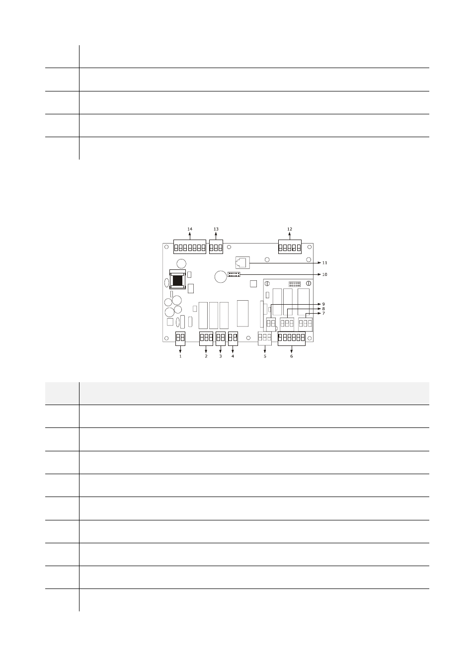
The following drawing illustrates the aspect of the devices' control module.
The following table illustrates the meaning of devices' control module parts.
PART
MEANING
1 power
supply
2
K1 and K2 digital outputs
3 K3
digital
output
4 K4
digital
output
5
digital output K5
6 digital
inputs
7 K8
digital
output
8 K7
digital
output
9
digital output K6
This manual is related to the following products: